The heading “Chronograph”, covers a vast number of applications, but the fundamentals are very similar. The chronograph is, as its name implies, a recorder of time and it is usual to apply the word chronograph to a watch toinstrument, it may be a clock, which tells the time of the day and also has fitted to it a mechanism which can be put into operation at will to record an interval of time. A watch that records an interval of time only is called timer. The mechanism which is put into operation to record an interval of time, whether it is fitted to a chronograph proper or a timer, is similar in each case. We shall, however, deal with the chronograph first.
Up to recent years, the operation of the chronograph was form one push, usually at the winding button. One push to start the chronograph hand running, second push to stop, and the third push to return to zero. The modern chronograph – largely in the form of a wristwatch – is fitted with two pieces. One of the push pieces is to start and stop the chronograph mechanism and the other push piece to return to zero, there is a variation of this, one push to start and the other to stop and return to zero.
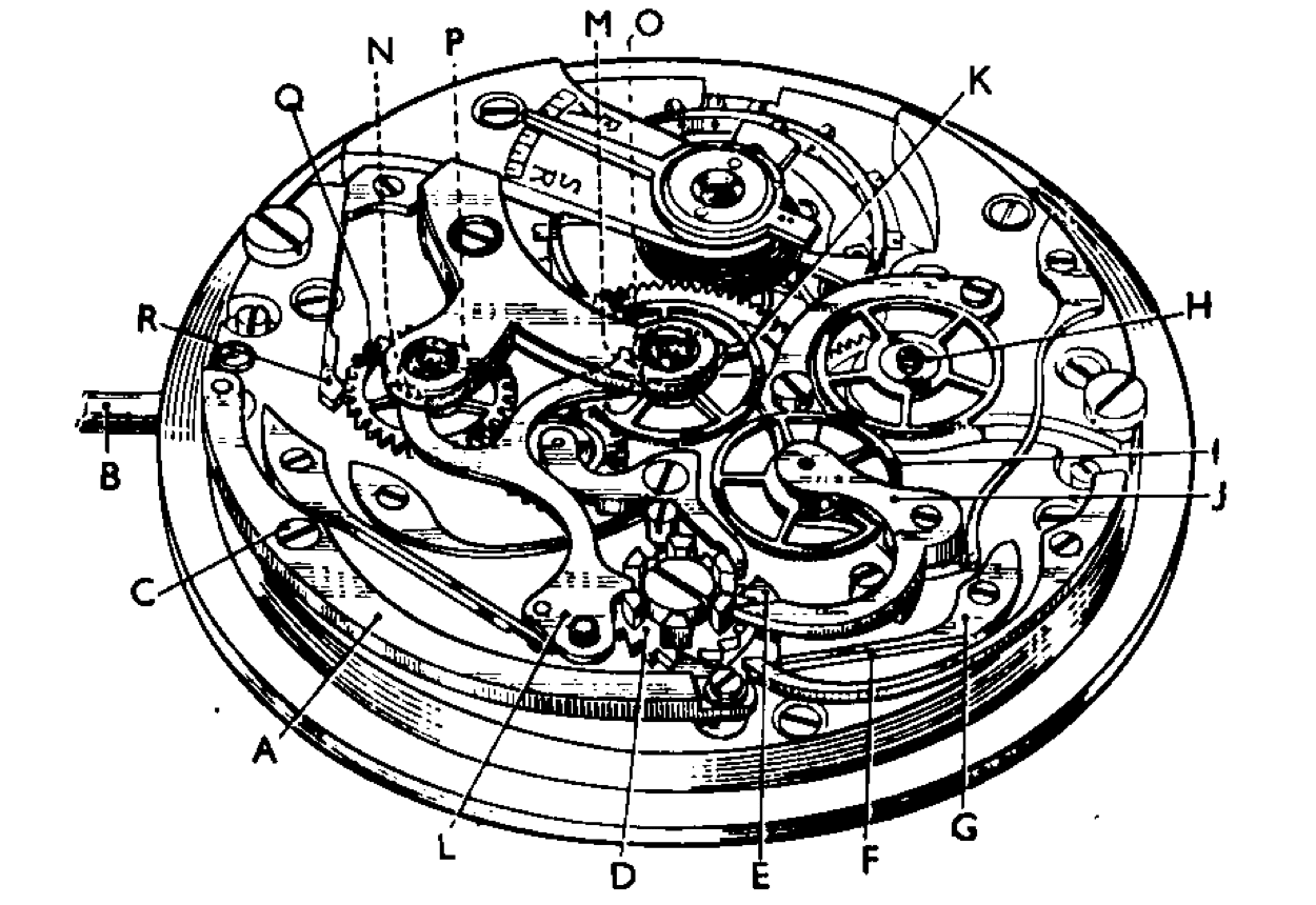
The illustration Fig. 86 is of the three push from one push piece type, and to describe the action of this, gives the fundamental principle of all chronographs. The lever A is pushed in at B by the action of push pins at the end of the winding button – or the button itself sliding on the winding shaft – this contacts a steel tube which impinges upon a stud riveted to the lever A. As this lever pivots at the shouldered screw C, it pulls round the column wheel D by means of the pawl E. When the tooth of the column wheel has been gathered up, the lever A returns to its normal position under the tension of the spring F, and the column wheel is held in position by the jumper spring G. The wheel H is fitted friction tight on the extended pivot of the fourth wheel and is in constant gear with the wheel I, which is pivoted on to and carried by the lever J.
As the nose of the lever J drops between the castellated column wheel it allows the wheel I to gear into the chronograph wheel K and so the chronograph wheel hand, which is fitted to the pivot of the wheel K, starts to rotate.
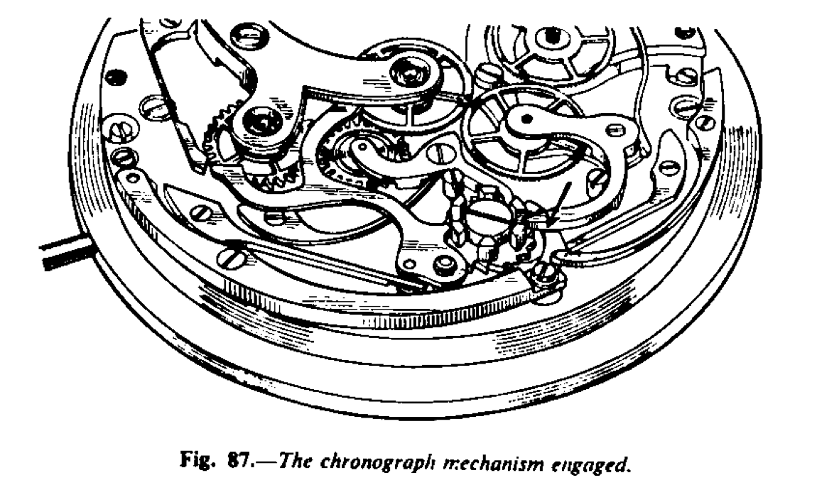
As the castle wheel rotates one ratchet tooth, the lever J will drop between the castellations or columns as indicated by the arrow in Fig. 87, and the wheel I will be in gear with the wheel K.
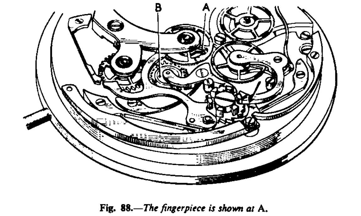
A second push on to the winding button will cause the column wheel to rotate and lift up the lever J indicated by the arrow in Fig. 88, and so disconnect the wheel I from the wheel K, and the chronograph hand will stop. Thus a reading of the duration of the run can be observed by the position of the hand pointing to the scale on the dial.
A third push of the button will cause the column to rotate and the lever J will stay on the block of the column wheel and the lever L will drop between the blocks, and in so doing, the end M and N will contact the heart pieces O and P, and return these two wheels to the zero position. Heart pieces are fixed to both the chronograph wheel and the minute counter.
Minute Counter
The wheel Q is the minute counter and has fitted to its extended pivot the minute counter hand. This wheel is held in position during operation by a jumper spring, R (Fig. 86). A fingerpiece A (Fig. 88) is fixed to the chronograph wheel and as it revolves it contacts the wheel B (Fig. 88) and moves in on one tooth. This wheel gears into the minute counter wheel and it moves that wheel one tooth, so that for each revolution of the chronograph wheel the minute counter wheel is moved one tooth and the hand fixed to it points the number of revolutions of the chronograph wheel. In other words, it counts the minutes.
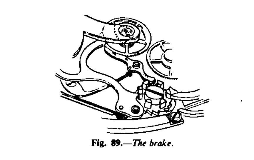
Some chronographs are fitted with another level, as in Fig. 89.
This is the brake. When the chronograph mechanism is at the stop position, the lever drops between the column blocks and the curved end with a radius exactly similar to that of the chronograph wheel, touches the periphery and so holds that wheel firm. The advantage is that if there is an interval between the stopping of the chronograph and the reading, there is no fear of the wheel moving, owing to vibration, etc. causing an incorrect registration to be made. When the chronograph mechanism is at zero and start, the brake is held on the top of the column blocks and so clear of the chronograph wheel; it only comes into action at the stop action.
Studying the Action
Before dismantling the movement, even before removing it from its case, carefully study the action of the mechanism. The beginner should spend at last five minutes observing what takes place when the chronograph is set in motion. Five minutes may not sound a long time, but just to watch and study, it is a good time and time well spent. Before even starting to take the movement to pieces, the student should be fully conversant with each part and know what takes place when the different parts are brought into action. The competent craftsman is able to reassemble the movement should it be handed to him completely dismantled and the parts shaken up to ensure thorough mixing. He would be able to assemble with ease because he knows how the watch works. With all complicated work, from the simple chronograph to the triple complicated movement, you must first know what you are doing. This is the secret of success with all complicated work.
Having thoroughly acquainted yourself with the action of the mechanism, procced to dismantle it. When a part is removed, say a spring, associate its screw with it. Screw may be of different lengths, even if the heads are of the same size, and to keep them in order is to save time eventually and may well prevent damage. It is not practicable to give a sequence order for dismantling; there is not many types of chronograph, that no good purpose would be served. One or two broad hints may, however, be given. For instance, most springs working on levers, etc., are int tension. Therefore unscrew a little so to enable the spring to be lifted out of action and relieve the tension before finally unscrewing, otherwise there is risk of the spring flying when it is unscrewed. See that the top parts are removed first, do not blindly unscrew all screws, but dismantle systematically.
Special care should be taken not to touch the heads of the eccentric studs; they have heads with slits just like screws for which they may easily be mistaken. To touch these studs means
re-adjustment. See Fig. 110 where eccentric studs are numbered 1 to 4.
Cleaning
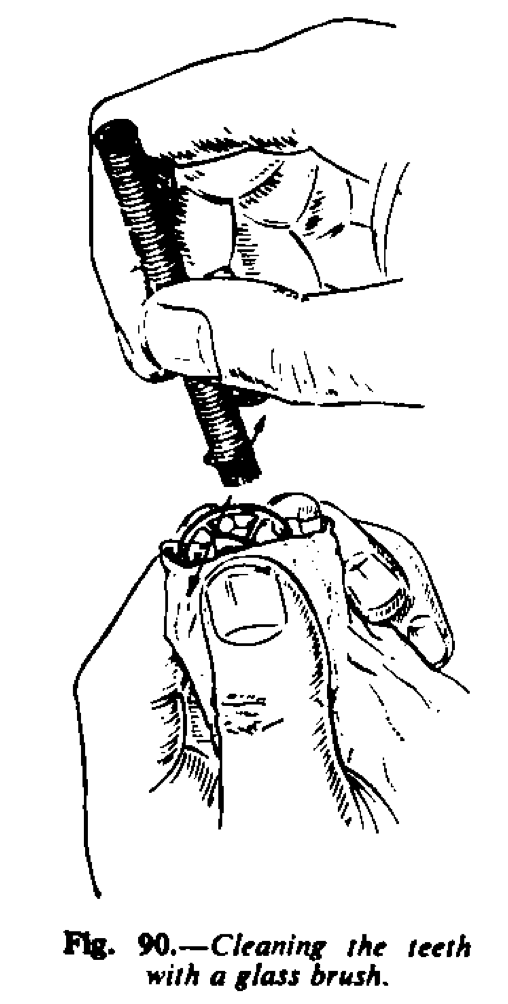
Having dismantled the movement, clean all the parts in the conventional manner (see ” Practical Watch Repairing ”). Well peg out the holes in the levers and see that the studs into which they fit are perfectly clean and free from congealed oil. The teeth of the fine-toothed chronograph wheels are cleaned with a glass brush, in addition to the usual cleaning with the machine or with benzine. These brushes can be purchased from the tool dealer and consist of a bundle of fine threads of glass bound together with string. Hold the wheel in tissue paper, between the thumb and first finger of the left hand, and with the end of the glass brush, brush the teeth as shown in Fig. 90. Continue to brush until the metal between the teeth glistens, then move the wheel round a little and brush again. Continue thus until all the teeth of the wheel are perfectly clean and bright.
As the brush wears down, the string is untied to release a further portion of the threads ; it is advisable to use the brush with the glass short so that it is stiff and cuts well.
This treatment refers particularly to the very fine toothed wheels, usually the centre chronograph wheel, and in some watches all the chronograph wheels.
Assembling complicated Watches
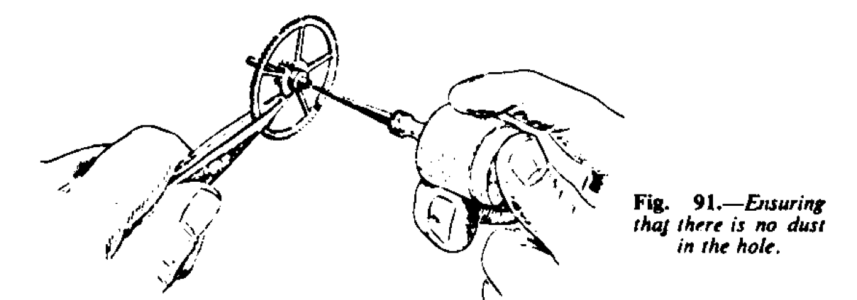
While cleaning the movement pay particular attention to the centre wheel of the going train. Fitted into the hollow centre pinion is a bush with a hole drilled into it to receive the lower pivot of the centre chronograph wheel. After this wheel has been through the cleaning machine, sharpen a piece of watch ped-wood to a long, thin and almost parallel point. Peg the hole from the end opposite to where the common pinion fits, using light pressure to avoid disturbing the bush. After the first application, scrape the peg clean and apply again, continuing thus until the peg leaves the hole clean. Then repeat the operation from the short end. When you are satisfied that the hole of the pinion (Fig. 91) and give several hard puffs. Repeat this from both ends. It is essential that both the hole in the bush and the hollow of the centre shall be free from dust.
If you have reason to believe that the hollow of the centre wheel is particularly dirty, it can be cleaned in the following manner. Stand the centre wheel upright on the end of its pinion, cannon pinion end up, in a bath of perfectly clean benzine, which is sufficiently deep to cover the uppermost end and leave it there for at least 30 minutes. It will be found that this procedure will remove all dirt and old oil from inside the hollow.
Having cleaned the whole of the movement and assembled the train up to, but not including the escapement, proceed to assemble the chronograph mechanism. Before replacing ant of the chronograph parts, oil the pivot holes which will be covered by the parts.
First for the column wheel into position, applying a little clock oil to the shoulder of the screw. Next screw the tension spring into position. There are two systems of spring; one where the spring bears on the side of the arbor of the centre chronograph wheel, and the other where it bears on the under side of the minute counter finger piece or on to a boss fixed to the chronograph wheel. In the case of the former, see that the spring is positioned about halfway across the hole of the hollow centre pinion; this will give it about the required tension when the arbor is on position. Where the spring bears on to a flat surface see that the spring will be free of the centre chronograph wheel arbor.
Screw the minute counter intermediate wheel into position, having first fitted the wheel on to the lever and oiled the shoulder screw with a little watch oil ; also oil, with clock oil, the shoulder screw of the lever. Next fit the spring which operates on the last-named lever and apply a little clock oil to the nose of the spring. Screw into position the column wheel jumper spring and also the stop-start lever with the pawl attached ; oil the shoulder screw of this lever. As a general rule, it is better partly to screw down a spring and then to strain the spring carefully into position so that it works upon the part it is intended to before finally screwing down. If this procedure is adopted the risk of breaking the spring is minimized since the spring is not unduly strained ; the securing point of the spring gives as the screw is loose.
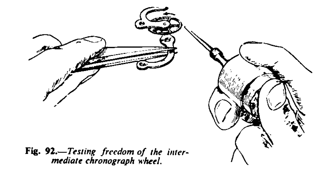
Next fix into position the intermediate minute counter wheel lever, having first screwed the wheel on to the lever, applying a little watch oil to the shoulder screw. Some chronographs are made with a cock T-screw to hold the intermediate wheel – the wheel is pivoted – in these circumstances apply a little watch oil to both pivots. Give the wheel a puff with the bellows, directing the air on to the sides of the teeth (Fig. 92) to ensure that it spins freely. Then apply a little clock oil to the shoulder of the lever screw and screw the lever into position. Fit the spring operating on this lever and apply a little clock oil to the nose where the spring impinges on the lever. Operate the column wheel to see that the last assembled lever operates correctly and also to work in the oil. It is good practice always to try each part as it is assembled rather than to make a complete assembly and then find something somewhere is not correct ; this principle applies equally to all assembly work. Next fit the chronograph wheel on the extended fourth wheel and press carefully but firmly down ; remember you are a pressing on to the lower jewel hole. Then assemble the intermediate chronograph wheel on to its lever and very lightly oil both pivots with watch oil. Give the wheel a puff with the bellows to ensure that it is perfectly free and spins easily. Oil with clock oil the side of the screw on to which this lever pivots. Now fit the spring operating on this lever and apply a little oil to the nose. Operate the stop-start lever to see that all is functioning well.
Observe that the wheel fitted on to the fourth wheel pivot gears correctly with the intermediate chronograph wheel on the same plane. If the wheel on the fourth pivot is too high it must be pressed down a little until it is the correct height. It should gear the full thickness of the wheel ; if, for instance, it engages only half the thickness of the wheel there is the danger, when the end-shakes are opposite, of the teeth becoming disengaged. On the other hand, if the wheel is low, then remove the wheel and close the hole in the wheel slightly. Invariably, there is an extended hole or boss and this can be gripped in a wire chuck – it should fit the hole in the chuck tightly – and the draw-in spindle made to rotate a little, so as to close the hole equally ; this is important because the wheel coul be thrown out of upright and be made to run out of true in the round. Try the wheel on the pivot and if necessary to open the hole, broach from the underside with a round broach ; it is important not to remove any metal.
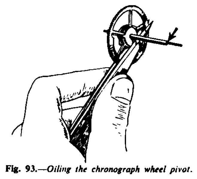
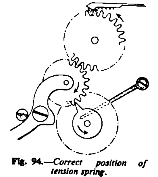
Hold the centre chronograph wheel as Fig. 93 and apply a minute quantity of watch oil to the shoulder of the lower pivot ; it needs only to be “ greased. “The Swiss generally advise that the pivots of the minute counter wheel and its intermediate wheel should not be oiled at all ; they argue that the action is light and practically frictionless and that oiling does more harm than good. Also with the same oiler, smear the underpart of the finger piece where the tension spring operates and then place the wheel carefully into position. Treat the pivot of the minute counter wheel in a similar manner and place that wheel in a position. When placing the centre chronograph in position it is advisable to check the position of the tension spring and this applies to the type of spring which bears on a flat surface and not on the arbor. Visualise the direction of rotation of the wheel ; the tension spring should be on the side of the arbor so that the wheel travels away from the spring and not towards it – disengaging and not engaging friction ( Fig. 94). Some plates are so recessed that it is not possible to assemble the spring on the wrong side.
Now screw on the cock holding the top pivots of the two last-named wheels. Try end-shakes of these wheels. If the tension is the type bearing on the flat surface of the finger piece or, as is sometimes the case, upon a boss, light downward pressure on the wheel Is applied and it should return by virtue of the upward pressure of the spring. To complete the assembly fit on to its post return to zero lever having first applied a little clock oil to the post. The spring of this lever not only acts as a spring but it also holds it down in position. Generally it is advisable to screw the spring into position first and then hold the nose of the spring to one side to allow the lever to drop down into position. See that this spring bears on the pin of the lever above the guide or boot. Apply a little clock oil to the nose of the spring.
I have advised oiling the pivots and the shoulders of shoulder screws of the chronograph wheels, i.e the intermediate and centre chronograph wheels and the intermediate and minute counter wheels. To repeat, some craftmen advise that these light-running wheels should not be oiled ; they reason that the oil drags and that there is little or no friction at these points. I cannot, however, bring myself to this point of view. I would rather say oil very lightly and with thin or light oil.
Testing Chronographs
The stage of assembly is now reached when the chronograph mechanism can be tested as a whole. First of all press the stop-start lever so that the mechanism is at stop, i.e the intermediate wheel and the return to zero lever are free of the centre chronograph by an arm ; never touch the teeth of any chronograph wheel with a metal tool : they are so delicate and very easily damaged ; sometimes the damage can be so slight as to be hardly discernible, but disastrous to good running.
Lead the wheel round and see that the finger piece is quite free of the intermediate minute counter wheel and that the point of the heart cam is free of the head of the return to zero lever.
Now depress the start-stop lever to bring the return to zero lever into action and with the same pointer move the centre chronograph wheel so that the head of the return to zero travels up the sides of the heart piece. Move the wheel, say , a quarter of a turn and release ; the lever should return the wheel to the zero position smartly. Then move the wheel and try to make the head of the return to zero lever remain stationary on the point of the heart piece and then allow the wheel to return very slowly. For this part of the test to be correct it should not be possible for the heart piece fixed to the centre chronograph wheel to remain stationary in any position. There should be no dead point.
Should the return to zero lever stick, examine closely to discover why. There are two or three reasons ; one is, the shape of the heart cam itself. Generally, an incorrectly-formed heart cam is most unusual. The heart cam of the modern chronograph is carefully and mathematically plotted so that there are no “dead” points. The form of the curve on each side of the heart cam is the logarithmic curve or an Archimedean spiral and it is considered that the logarithmic curve is the more perfect. The heart piece cam is very hard and it is not likely that it can change shape unless it is will fully altered. It is advisable, therefore, not to be tempted to touch the heart cam in order to alter its shape. If the edges of the cam show signs of damage, such as a bruise or burr, very carefully stroke the side with an Arkansas stone, only sufficient to remove the blemish, and then burnish well. Examine the head of the return to zero lever and see that it is free of blemishes; here, again, if there are any marks, care- fully stroke and burnish, making sure not to alter the original form or angle.
Should both the cam and the head of the lever appear to be correct the trouble may be in the angle of the head of the return to zero lever. To be correct the flat end of the head should be cut at an angle of 45 degrees from the line of centres (Fig. 95) or as near this angle as possible. The end of the head should be perfectly flat (from end to end, not the thickness of the lever); it should not be curved and neither should there be any rounding off of the ends. It should be just perfectly flat and sharp as in Fig. 96. Continuing the test, touch the chronograph wheel very lightly by an arm and see that the return to zero lever is holding it firmly. Now try the minute counter wheel and see if the lever is holding this firmly, too. If there is a slight movement of the minute wheel counter because the head is not quite hard against the apex of the heart, it is not material since the jumper spring will hold this wheel and in any case the reading of the hand on the dial is not critical. It is the centre chronograph wheel which must be firm so that there is no ambiguity about the zero position of the chronograph hand.
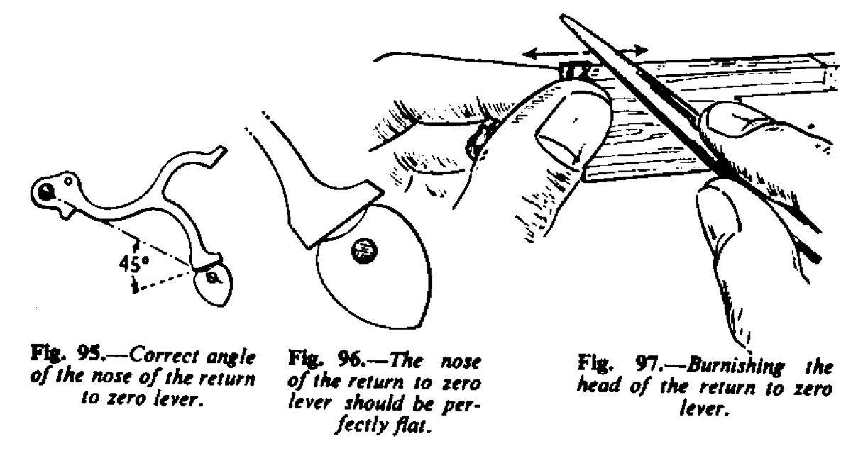
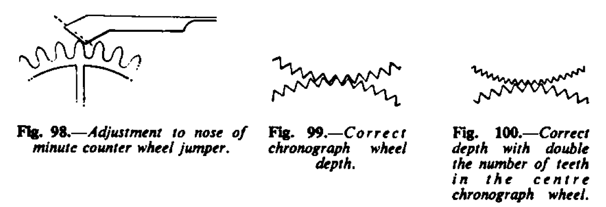
If, on the other hand, the minute counter wheel is firm and there is the slightest movement of the centre chronograph wheel, then the head of the minute counter part of the return to zero lever must be reduced. To do this, stroke with an Arkansas slip, making sure to keep the angle as originally, then draw stroke with a 3-0 emery stick and finally burnish with an oval burnisher, using a draw file motion along the length of the head (Fig. 97). With the return to zero lever down on the heart pieces, see that the head of the jumper spring of the minute counter wheel is between two teeth. Otherwise, when the lever is lifted free of the heart piece the minute counter wheel will move by virtue of the jumper spring bringing the wheel into position. If it is found that the head of the jumper spring is lifted then the spring must be moved slightly so that the V of the head is safely between the teeth. Sometimes the jumper spring is adjustable and can be moved with ease, but if there is no form of adjustment the side of the head must be stoned so as to allow the V to drop in. Fig. 98 shows the fault and the dotted line the correction, but before altering the shape of the head, observe the minute counter action to be explained later.
Chronograph Wheel Depth
Next it is necessary to assemble the escapement before the chronograph examination can be completed. Wind up the mainspring and press the button to start the chronograph running. Examine with the double eyeglass the depth of the intermediate chronograph wheel with the centre wheel ; to be correct the depth should be as in Fig. 99. Some chronographs are made with the teeth of the centre chronograph wheel the same pitch as the intermediate wheel and others are made with double the number of teeth in the centre wheel (Fig. 100).
It is more usual for the centre wheel to have double the number of teeth and it is better so because it is not so difficult to make intersection without movement of the centre wheel. If the pitch of both wheels is coarse there is the possibility of the intermediate wheel pushing the centre wheel backward or forward, before correct gearing takes place and therefore an accurate reading of the chronograph hand on the dial is not possible. Observe very closely the precise moment when the intermediate wheel is released and gearing takes place; if the teeth of the inter- mediate wheel do not immediately drop between the centre wheel teeth then the wheel fitted on to the pivot of the fourth wheel must be moved round slightly. To consider an extreme case, the points of the teeth may meet and it may be one or two-fifths of a second before the gears settle down; or it may be a fifth of a second because the teeth intersect on the sides of the teeth; they should drop in fully to be correct and this can be attained by adjusting the wheel on the fourth wheel.
Some chronograph adjusters start by setting the depth of intermediate and centre chronograph wheels so deep, by means of the eccentric plug on to which the lever carrying the intermediate wheel banks, as actually to stop the whole watch running and then to turn the plug until the train starts to run and a full arc of vibration of the balance is obtained. It is said then that the correct depth is made. It is true that this depth should be as deep as possible so as to minimize the backlash of the centre chronograph wheel in order that the tension spring shall be light as possible. But it is to be preferred, and is safer, that the depth should be seen, as already noted. Let the chrono- graph run, under close observation of the depth, for at least one minute, to ensure that there is no “bad depth,” due, perhaps, to want of truth in the round of one of the wheels.
When satisfied with this part of the test, pay attention to the minute counter mechanism. As the finger piece comes round to move the intermediate minute counter wheel, see that it enters between the two teeth freely. The point of the finger piece must be free of the preceding tooth and it should travel round and move the wheel one tooth so that the head of the jumper spring is lifted up and over one tooth and the tension of that spring will complete the operation, the wheel will jump one tooth. As the finger piece is about to enter between two teeth, stop the balance with a pointed piece of pegwood. Then move the balance backward and forward so that the action of the finger piece can be observed accurately. See the finger enter, move round and touch the outgoing tooth and move it, observe the head of the jumper spring lift and the end of the tooth of the minute counter wheel pass under it; then to the finger piece again and see it about to disconnect and then the jumper spring take charge and move the wheel one tooth. This action is most important; many chronographs stop because of a faulty minute counter action and it is worth some close attention.
Several faults can occur here. It may be that the finger piece butts on the end of the preceding tooth before entry or the finger may move the wheel too far. If the jumper is adjustable, move the minute counter wheel round a little so that the finger enters freely and then observe as it disconnects. If the disconnecting is correct it indicates that the cure was with the jumper but if the finger moves the wheel too far it points to the fact that the finger is too long and must be shortened. On the other hand, if the intersection of the finger is shallow and it enters between two teeth freely but does not move the wheel far enough for the jumper to act, then the eccentric plug, upon which the intermediate counter wheel lever banks, must be turned to make it deeper. Should the entry of the finger be as deep as is safe, i.e. it just frees the preceding tooth but it does not move the wheel far enough the cure rests with the jumper as already explained.
It is necessary now to revert to the case where the jumper head was riding a tooth when the return to zero lever was pressing on the heart piece. First and foremost, the changing over of the minute counter must be correct and if this has been achieved by moving an adjust- able jumper or by stoning one side of the head of the jumper, it must not be altered to accommodate the condition of the head riding a tooth when at zero. Sometimes the one correction if there is an error will correct both faults. If you are left with the head riding a tooth then this must be corrected by altering the angle of the head of the return to zero lever operating on the heart cam of the minute counter wheel. To cite a specific case, if the jumper is as in Fig. 101, then stone the head of the lever in the direction as dotted line (the illustration is exaggerated). This will have the effect of moving the wheel round slightly and allowing the head of the jumper spring to rest between two teeth.
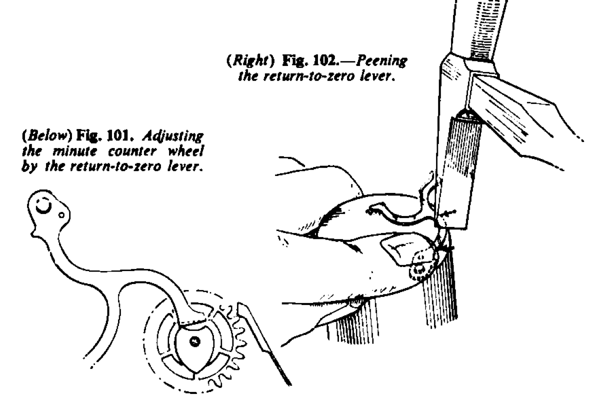
Start the chronograph running and observe, as the point of both heart cams rotate, that they are free of the heads of the return to zero lever. If they are not, then peen the side of the lever on the underside as shown in Fig. 102. Should the head operating upon the centre chronograph cam foul and the minute counter cam be free, the small amount necessary to “bend” the lever will not affect the minute counter cam materially. Hold the lever upside down on a flat steel stake in the vice and hammer with the peen of the hammer along the edge between the arrows (Fig. 102). The lever is held down flat but the peen strikes at an angle. Remove any bruises the hammer may have made by stroking with an Arkansas slip. There is a method of “stretching” the part of the lever operating upon the column wheel, but this is not satisfactory because the “stretching” really consists of knocking up a burr and this burr soon wears down and the original fault prevails.
Running Test
With the dial and hands fitted on to the movement, and it is more convenient with the movement fitted into its case with the button and shaft in, make the following test.
Start the chronograph running and observe the actual start of the chronograph hand to see that it does not jump, as already explained. Then as the hand comes up to the 60 seconds observe when the minute counter starts to move. To be correct it should not move until after the chronograph hand has passed the 60 seconds mark. There should be no appreciable lapse; less than one-fifth of a second. The counter hand should not move at 58 or 59 seconds, but at the moment after reaching 60 seconds. To correct, if faulty, move the finger piece round slightly on the chronograph arbor. Hold the wheel in the fingers and twist the finger piece with brass-lined pliers in the desired direction.
If all the points described have been carefully attended to then, when starting, the hand should “step” forward smoothly; the minute counter hand should start to move immediately after 60 seconds and should complete its movement in under one second. When the chronograph mechanism is stopped the chronograph hand should stop dead-no slight movement backward or a slight jump forward; the return to zero should be decisive and both hands should fly back to zero smartly and dead on to the 60 seconds mark in the case of the chronograph hand and to the 30-minute mark the minute counter hand (or to the zero mark, the minute counter may be 15, 45 or 60 minutes).
Finally, complete the oiling. Apply a little watch oil to the top pivots of the centre chronograph and minute counter wheels; a trace of watch oil to the head of the minute counter jumper spring; just grease with clock oil the faces of the heads of the return to zero lever, so that the edges of the two heart cams are slightly greased; a little clock oil to the blocks of the column wheel.
Vital Points in Repair
Important points concerning all chronographs :-
The teeth of chronograph wheels must be cleaned with a glass brush.
The depth of the intermediate chronograph into the centre chronograph wheel must be correct.
The operation of the minute wheel counter by the finger piece must be correct.
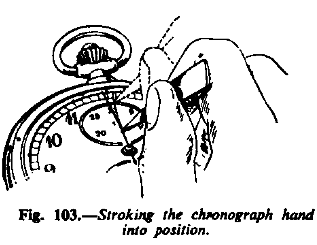
The chronograph hand must fit tightly and be placed into position -with the return to zero lever on the heart cams-pointing exactly to the 60 mark, not even the thickness of a one-fifth second mark off. Sometimes if the hand is a hairs’-breath off, the hand can be “stroked” into position. With brass tweezers stroke the hand in the direction required, as indicated in Fig. 103. The bend, an extremely slight curve, is not discernible to the eye. On no account should the hand be bent so much that the bend is obvious; in these circumstances it is better to remove the hand and fit again.
With the chronograph running, and the watch held close to the ear, you should be able to hear the chronograph “sing,” i.e. a slight ringing noise owing to vibration of the chronograph hand.
I have discussed, at some length, perhaps, what may appear to be trivial points, but all of them are vital to the correct functioning of a chronograph. They are the fundamental adjustments of all chrono- graphs, split-second chronographs and timers.
Wrist Chronograph Systems
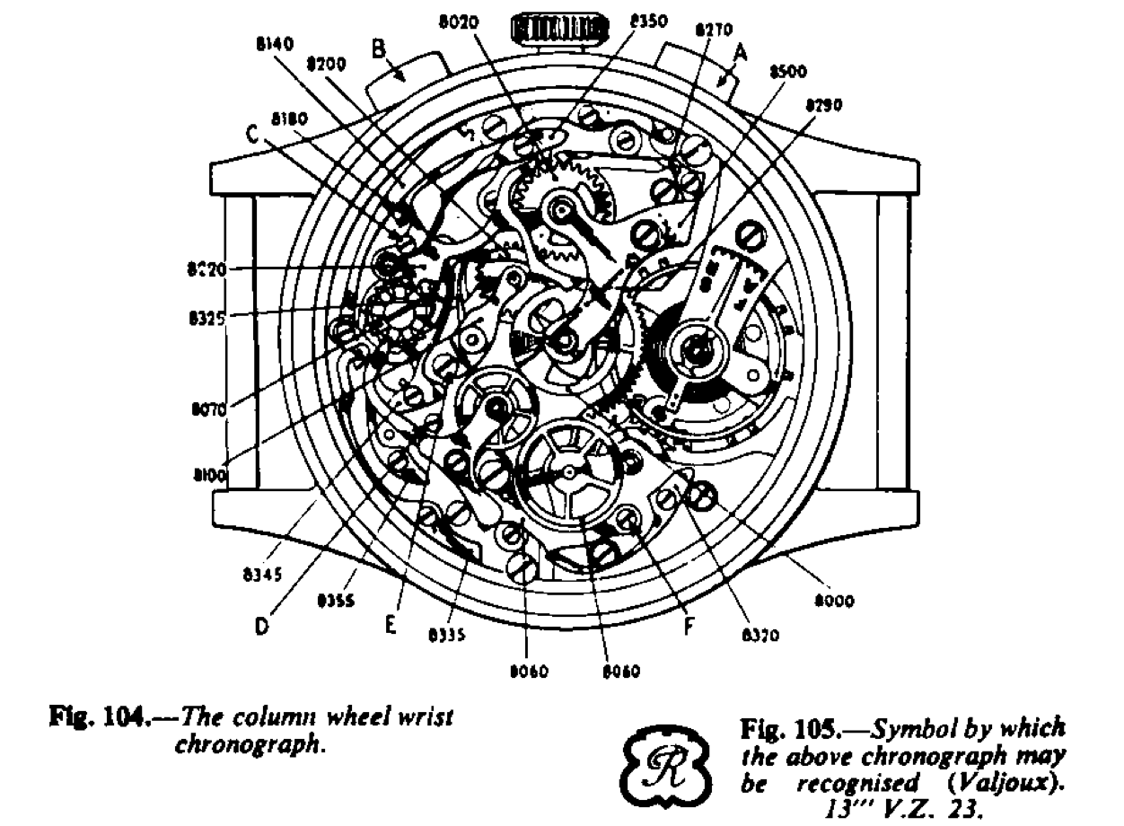
The majority of chronographs passing through the workshops to-day are wrist watches and most of these are on the two push-piece system (Fig. 104). This calibre, with column wheel, is made by the Ebauches factory, Valjoux, S.A. of Les Bioux, Switzerland. It will be found in various standards of finish, i.e. qualities, according to the finishing factory who handle it and they, in all probability, will give the movement a name. The push-piece A starts the chronograph train running and a second push on the same piece will stop it.
A second push on the push-piece A will start the chronograph running again from where it was stopped; the hands will not have returned to zero. This can be an advantage where an intermittent recording is required, such as to check the time of flow of liquid. The flow. starts and the chronograph is set into action, then there is a hold-up in the flow, maybe to fill another container, and the chronograph is stopped. The flow starts again and the chronograph is set into action. In this manner the amount of liquid used-the rate of flow is known -can be ascertained without calculation.
A push on B will return the hands to zero. Other than the two- push pieces and the additional lever C the mechanism is exactly similar to the one already described. The calibre is also made with one- push piece, i.e. triple action from the one-push piece.
The screw heads of the plugs D, E and F are eccentric and control the depth of action of the levers bearing upon them. They should not be moved during dismantling and cleaning, but they may have to be turned when adjusting, as already explained.
The manufacturers recommend the following order of assembly. The numbers given to the parts are those of Ebauches S.A., Neuchâtel, Switzerland, to whom we are indebted for the illustrations of this model and the two calibres which follow. If a new part is required it is necessary to quote the number only, which in this case is 13″ V.Z.23. Irrespective of the name on the movement, the calibre can be recognised by the trade mark letter R in a shield as shown in Fig. 105.
Assembly of the Valjoux Chronograph
The order of assembly, and in reverse to dismantle, is as follows:-
1. The friction or tension spring 8290.
2. The intermediate minute counter wheel assembly 8100 and spring 8325.
3. Minute counter wheel 8020 and centre chronograph wheel 8000 and then the cock 8500.
4. The minute counter wheel jumper 8270.
5. The column wheel 8070 and its jumper spring 8355.
6. Return-to-zero push lever 8180 and start-stop lever 8140 and its spring 8335.
7. The brake lever 8200 and its spring 8345.
8. The intermediate lever assembly and its spring 8320.
9. The wheel fitted on to fourth wheel pivot 8060.
10. The return-to-zero lever 8220 and its spring 8350.
This factory recommends the oiling of all chronograph wheel pivots, with the exception of the minute counter wheel pivots and the inter- mediate minute counter wheel pivots. Finally, apply the tests as noted on page 75.
It is the common practice with all Swiss factories to indicate a left- hand screw by cutting two additional slots on the head. These are a lighter cut, on each side of the centre slot (Fig. 106).

Two-push Chronographs without Column Wheel
The two-push chronograph without column wheel shown in Fig. 107 is made by Le Landeron, of Le Landeron, Switzerland. The trade mark or sign of this factory is the letter L in a shield as shown in Fig. 108 and as with the Valjoux, the movement, no matter what name has been given to it, can be recognized this sign.
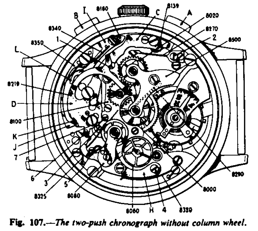
There is no column wheel. The push A starts the chronograph running and the push B stops and returns to zero. The first push on B stops it and the second push on B returns the hands to zero. The action is quite simple and is as follows:-
Push-piece A operates on the lever C and this lever engages in the slot of lever D. Fitted to this lever is the screw 6 and fixed to the lever 8100, which carries the intermediate minute counter wheel, is the screw 7; both screws 6 and 7 are not ordinary screws and they should not be turned. The screw 7 of the lever 8100 bears upon the lever C by virtue of its spring. The lever H, which carries the inter- mediate chronograph wheel, bears upon the screw 6 of the return-to- zero lever D so that when the lever C is depressed the lever D swivels upon its stud and is drawn away from the centre and at the same time the lever 8100 draws from the centre and the lever H drops towards the centre. Thus the return-to-zero lever and the intermediate counter lever are drawn from the centre chronograph wheel and the intermediate chronograph wheel engages with the centre chronograph wheel and the mechanism is set into motion. To stop the chronograph running, the lever I is depressed when the push B is used. This lever depresses the lever C which in turn moves the lever D. This lever is controlled by the jumper spring J working in the notches K and one press of the push B allows one notch to pass, sufficient movement has been given to the lever D to disconnect the gears of the chrono- graph wheels and consequently the centre chronograph wheel stops. Upon releasing the push M the lever I returns to its normal position by virtue of its spring. By this time the lever D is in such a position that upon a second push of the push-piece B, the end of the lever I at L is able to press the lever D down and by reason of the jumper action it snaps home and returns the heart pieces to zero. It is a most ingenious piece of designing, simple and definite in action.
The screw heads marked 1 to 7 are not ordinary screws, they are eccentric plugs and should not be moved. They are used when it is necessary to adjust a depth or change of position of the part bearing upon them.
Assembly of the Landeron Chronograph
The numbers in the illustration (Fig. 107) are the numbers given to the parts by the Ebauche manufacturer, and when ordering a new piece it is necessary to give the number only and the calibre name and number.
The order of assembly, and in reverse to dismantle, is as follows:-
2. The intermediate minute counter wheel 8100 and its spring 8325.
3. The minute recording wheel 8020 the centre chronograph wheel 8000, and then the chronograph cock 8500.
4. The minute recorder wheel jumper 8270.
5. The starting lever 8139. 6. The return-to-zero push lever 8219.
7. Stop return-to-zero push lever 8180.
8. The springs 8340 and 8350.
9. The intermediate chronograph wheel lever assembly 8080 and its spring 8320.
10. The wheel fitted to fourth wheel pivot 8060.
Finally apply the tests as noted on page 75.
The chronograph shown in Fig. 109 is, like that shown in Fig. 107, a two-push-piece model without column wheel. The ébauche is made by Venus S.A., Moutier, Switzerland, and can be recognized by the sign of a star in the shield as shown in Fig. 110, no matter what name has been given to the movement. The design is however different to the Le Landeron described. The push A starts and stops the chronograph running and push-piece B returns to zero.
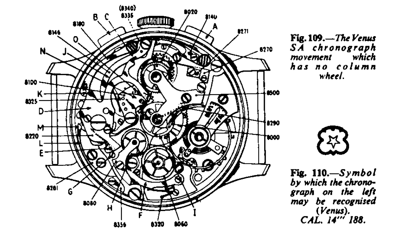
The action is as follows:-
Pressing the push A depresses the lever C and the end of this operates on a cam with a part shaped like ٨. The first plunge takes place on the left-hand side of the A and it causes the return-to-zero lever D to draw away from the centre, and at the same time, the end of the lever E releases the lever F, where the screw G, fixed to the lever F, has been resting on the lever D at E. This movement allows the intermediate chronograph wheel H to gear into the centre chronograph wheel I and so the chronograph mechanism starts to run. Another push on the push-piece A and the end of the lever C presses upon the other side of the A shaped part, because the point of this part has been brought to the left side of the lever C by reason of the first push. The lever D is therefore pushed towards the centre and in so doing the end E contacts the screw G and pushes the lever F away from the centre and the intermediate chronograph wheel is disconnected from the centre chronograph wheel and the chronograph mechanism stops.
When the piece B is depressed the pin of the lever J contacts the lever D at K and pushes it towards the cent and the two ends return the heart-piece to zero. Also at the same time, the lever N carrying the intermediate minute counter wheel O is drawn away from the centre and therefore the finger-piece fitted to the centre chronograph wheel is disconnected with the intermediate counter wheel. The snap effect is obtained by the jumper spring L operating upon the notches at M cut into the A cam and fixed to the lever D.
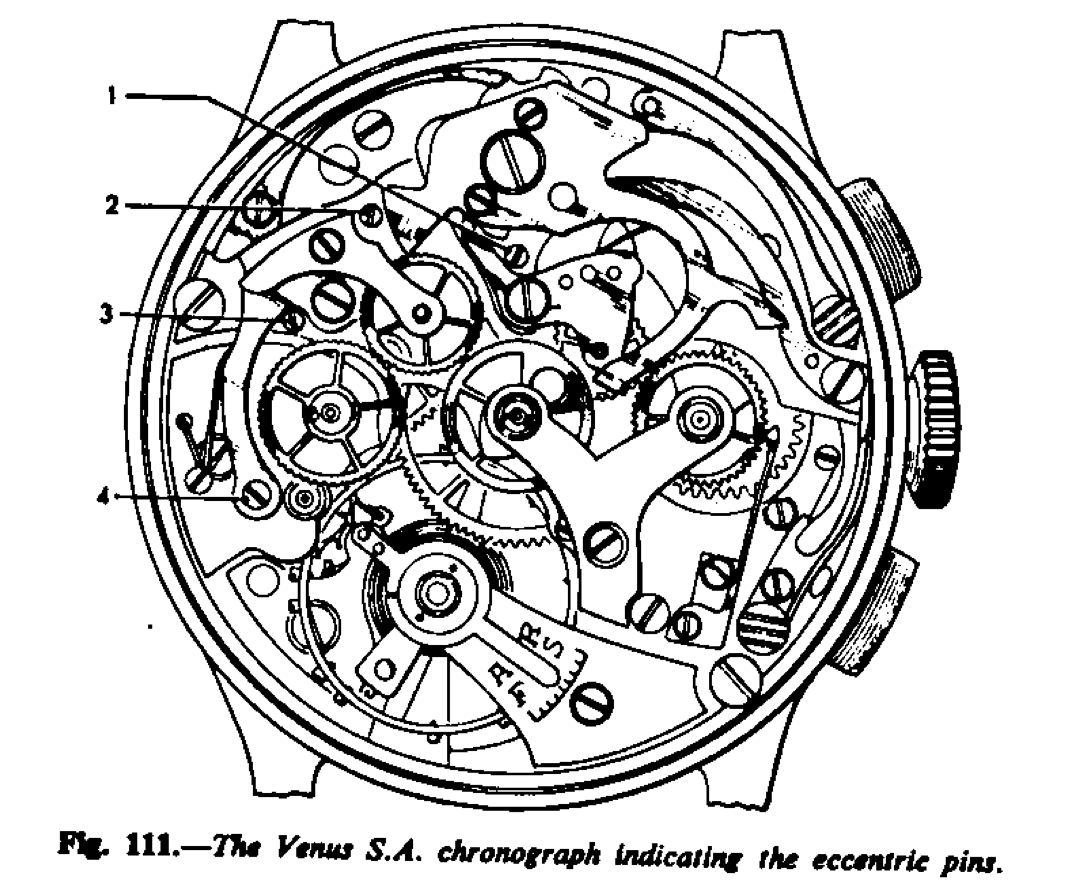
The screw heads 1 to 4 (Fig. 111) are eccentric plugs and should not be turned; they are for adjusting the depth, etc., of the parts bearing upon them.
The numbers notes in the illustration (Fig. 109) are the numbers given to the parts by the ébauche manufacturer, and when ordering a new part quote the number only and the calibre name and number.
Assembly of the Venus Chronograph
The order of assembly, and in reverse to dismantle, is as follows:-
1. The lever spring 8335 and the plate 8281.
2. The tension spring 8290.
3. The intermediate minute counter wheel assembly 8100 and its spring 8325.
4. The minute counter wheel 8020 and the centre chronograph wheel 800 and then the chronograph cock 8500.
5. The minute counter wheel jumper spring 8270.
6. The stop-start lever 8140 and the lever 8180 and the lever 8146.
7. The return-to-zero lever 8220 and then the jumper spring 8356.
8. Check action of stop-start lever 8146 through hole in lever 8220.
9. The intermediate chronograph wheel assembly 8080 and its spring 8320.
10. The wheel fitted to pivot of fourth wheel 8060.
Finally apply the tests as noted on page 75.
Chronograph Dials
The uses to which chronographs can be put are almost legionary. Various calculations are made and the dial calibrated so that the user himself has no need to make calculations; all he has to do is to select the chronograph with the dial to suit his purpose, “press the button,” and the exact answer is shown on the dial. The main dials of different calibrations are illustrated here, and they form a useful reference. But the dials shown are not the complete range, if the dials of timers are included. Later on timers will be described and a range of dials illustrated.
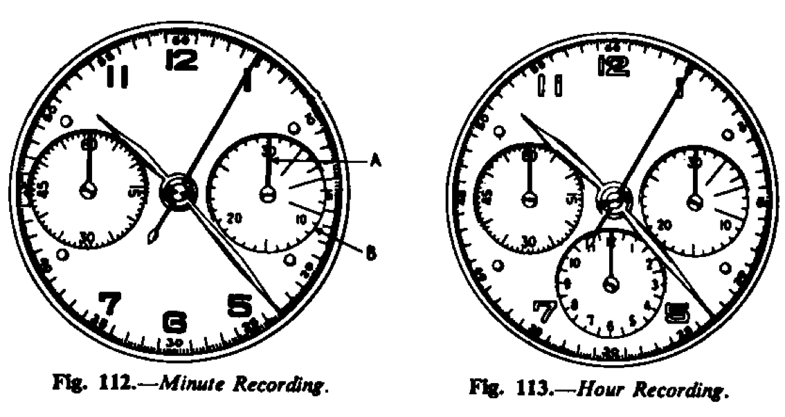
Fig. 112.-Minute recording chronograph; On the outside is the 1/5th of a second circle. A is the minute counter and B three-minute divisions to time the length of telephone conversations.
Fig. 113.-Hour recording chronograph; In addition to the minute counter dial with the timing of telephone conversations, is the dial between 7 and 5, calibrated to record hours, up to 12.
Fig. 114.-Tachometer chronograph ; The word “tachometer” is from Greek “ Takhus”, swift. The tachometer circle is calibrated to record the speed of a moving object, such as a motor car, aeroplane, etc. over a known distance. The standard distance upon which the calibration is made is shown on the dial as “Base 1,000 metres, “ or “Base 1 mile,” etc.
The push to start the chronograph running is pressed as the object to be timed passes the starting point, and the hand is stopped when it reaches the finishing point. The chronograph hand will then indicate the speed in miles or metres per hour.
Fig. 115.-Telemeter chronograph ; The word “telemeter” is from the Greek “Tele”, far off, at a distance. The telemeter circle, outside the seconds scale, is calibrated to measure the distance an object, or a phenomenon, is from the observer, provided the object is visible and audible. The calibration is based upon the speed of the sound through the air, i.e. approximately 1,115 feet or 340 metres per second.
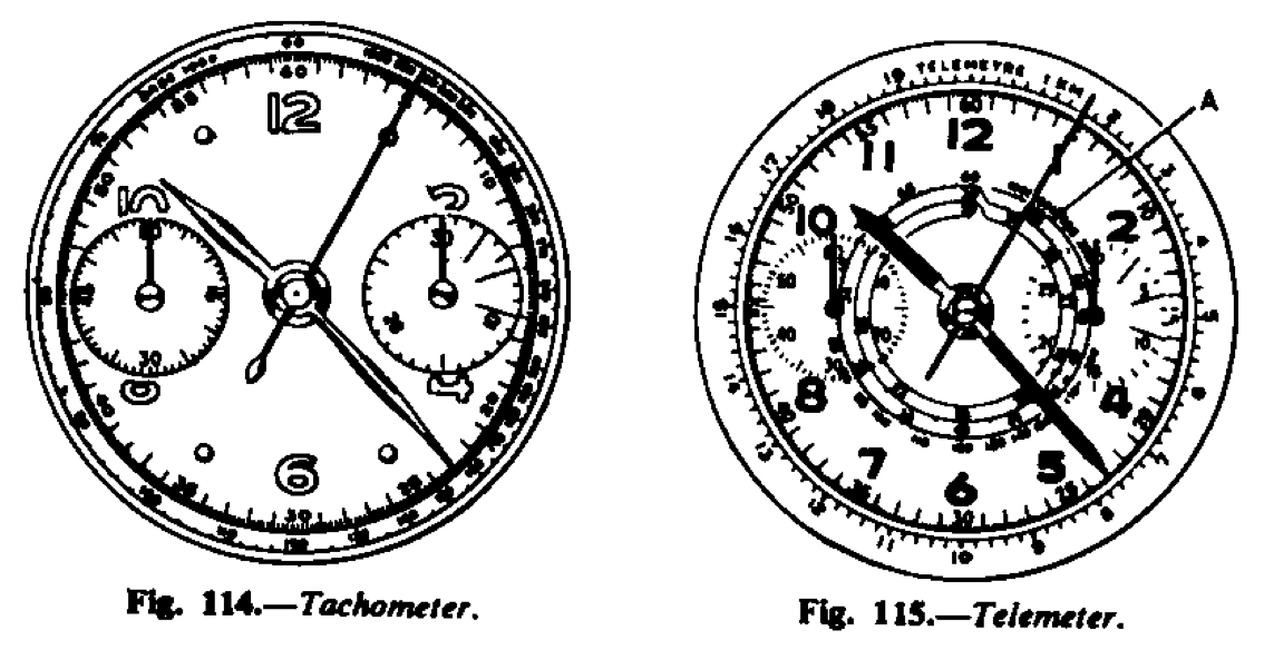
If, for instance, the chronograph is started when the observer sees the flash from a gun, and then stops it when he hears the report, the chronograph hand will then record the distance of the gun from the observer in miles or kilometres, according to how the dial is calibrated. Similarly, if the chronograph hand started when a flash of lightning is observed, and stopped when the thunder is heard the hand will indicate the distance of the storm from the observer, since lightning and thunder are simultaneous.
This dial is also calibrated as a tachometer, A. With this form of the calibration the reading is as follows. If the minute recording hand points to 0 the speed is as shown in the outer circle, i.e. between 60 and 1,000 kilometres. If the minute counter points to one minute, i.e. one complete revolution of the chronograph hand , the reading is as shown in the middle circle, between 30 and 60, and if the minute counter hand points to two numbers, then the reading is as shown on the inner circle between 30 and 20. Therefore, if the object being timed takes 60 second to travel 1 kilometre it will be travelling at a speed of 60 Km. per hour ; if it takes 2 minutes, 30 Km. per hour ; and 3 minutes, 20Km. per hour. This particular tachometer scale is marked in kilometres and intended for a kilometre base, but it will serve the same purpose for a mile base, and the scale reading should then be taken as miles. The base can, in fact, be any unit distance, and the scale read off the same units.
Fig. 116.-Pulsimeter chronograph ; the circle indicated on the edge of this chronograph dial is a calibrated for the purpose of pulse taking. The chronograph is started when the counting begins and at the 16th beat (or after 15 beats) the chronograph is stopped. The reading on the scale gives the number of pulse beats per minute. Dials are calibrated also to take 30 and 20 beats.
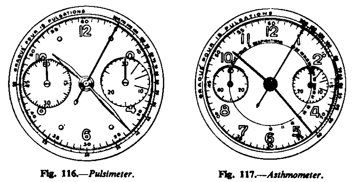
Fig. 117.-Asthmometer chronograph; The word “asthmometer ” is taken from the Greek “Asthma,” panting. The chronograph is started as the respirations are counted, and upon the expirations of the 5th, 10th, 15th, 20th and 25th respiration, according to the basis of calibration indicated on the dial, the chronograph is stopped. The reading on the scale indicated by the hand then shows the number of respirations per minute.
Fig. 118.-Production-counting chronograph; The object of this scale, on the outer edge, is to determine the number of articles or operations, produced per hour. The production circle is calibrated so that if the hand is started at the beginning of the production of an article, or of an operation, and stopped upon completion, the reading will give the number of articles or operations per hour. This state- ment is correct provided that the time is more than 5 seconds and less than 60 seconds. If the time is less than 5 seconds it is necessary to take as a basis several observations and multiplying the number of observations by the number shown on the scale. Should the pro- duction take longer than 60 seconds, then the time recorded will, of course, have to be divided into 60 minutes to give the rate of production per hour.
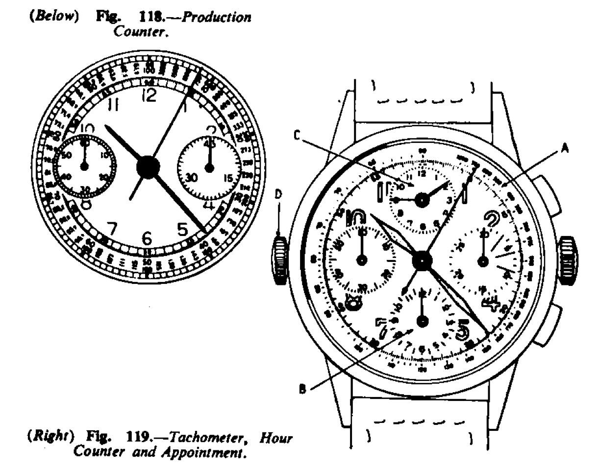
Fig. 119.-Appointment or memento dial chronograph; In addition to the tachometer scale, A, and an hour counter up to 12 hours, B. there is the dial C, where the hands are set by the button D, which forms a reminder of an appointment or event.
Fig. 120.-Multiple-purpose chronograph; This dial is calibrated with tachometer scale A, telemeter scale B, pulsimeter scale C, and minute counter, D, with 3-minute divisions for duration of telephone conversations.
Fig. 121.-Tide chronograph; The dial A is divided into 5-minute sections for the purpose of yachting. It gives at a glance the duration of the 5-minute warning signal before the start of a race. The dial B shows the time of high and low tides at any given place. The push- piece C is for setting this dial. The dial is divided into four sections, the darker sections (coloured blue on the actual dial) indicating high tide and the lighter sections (colored yellow on the actual dial) indicating low tide. The known high tide of a place is ascertained, usually at the coastguard station, and the dial is set accordingly; thereafter, while in the same place, the high and low tides will be indicated by the dial without further reference to the coastguard station.
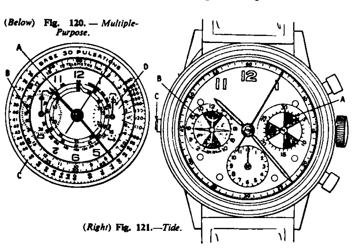
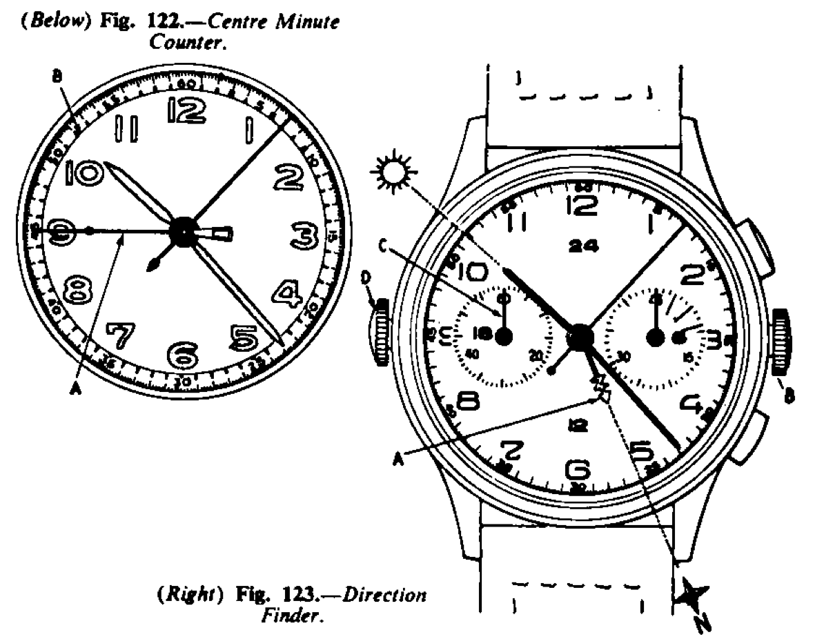
Fig. 122.-Chronograph with centre minute counter hand; In place of the normal minute counter dial, the hand A records the minutes up to 60 on the scale B.
Fig. 123.-Direction-finding chronograph; The hand A is first set to the known North with the aid of a compass by the button B. This hand rotates once in 24 hours. Thereafter if the watch is held horizontally with the hour hand pointing towards the sun the hand A will point to the North. In addition, the seconds hand C can be set to the exact second by pushing in the button D and turning, useful when it is required to set the watch to the exact second given by a time signal.
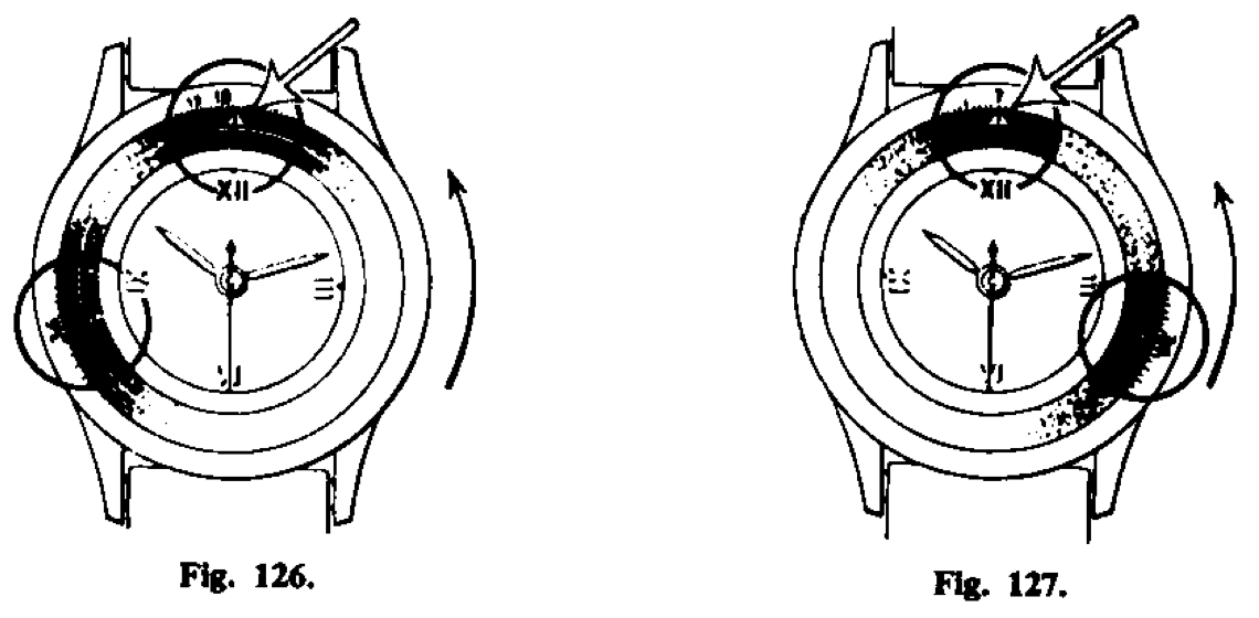
The calculating watch: Although the calculating watch is not a chronograph, or even a complicated watch, it should be put on record for its ingenuity. Made by Juvenia of La Chaux-de-Fonds, Switzer- land, it is in fact, a slide rule, made in a circular form, and can be used for all purposes to which a slide rule is put ; multiplication, division, finding roots and powers, etc. The illustration Fig. 124 gives the general appearance of the watch and Figs. 125 to. 127 show how it operates.
(1) To set. Turn the bezel clockwise until the pointer stops at 12 noon and then continue turning, until the multiplicand or the devisor appears in the radius of the pointer. Fig. 125-The figure 35 has been set.
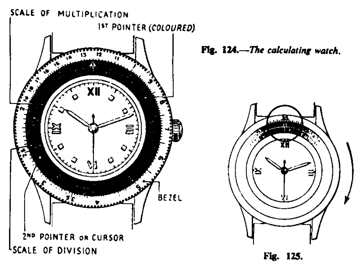
(2) To multiply. Turn the bezel anti-clockwise until pointer and multiplicand reach the multiplier, e.g. multiplying by 5. Fig. 126- 35 x 5 = 175.
(3) To divide, use the other scale. Read the result as shown in Fig. 127, 35+5+ 7. Fig. 126.
Split Seconds Chronograph
The split seconds chronograph is so called hands divide or split. This is, of course, not in fact one hand is superimposed upon the other; so that two records of time can be registered. Fig. 127. because the seconds strictly true because there are two hands The usual action is that when the chronograph mechanism is started the two hands rotate together as one. Upon depressing the split seconds push piece, one hand stops and the other continues to rotate. When the split push is depressed again the split seconds hand catches up the normal chrono- graph hand and again travels with it. Therefore the seconds are not split; if the train is an 18,000 one the seconds hands will indicate one-fifth seconds and there is no means of dividing that on this particular watch. The seconds hands themselves split or divide. The name, though cumbersome, should be “Dividing seconds hands watch.”
The action is quite simple and is as follows:-In addition to the normal chronograph column wheel is another similar wheel which can be made to rotate by the lever A (Fig. 128) and is controlled by the jumper spring B. Operating upon the upper set of the teeth of the column wheel C is the pair of levers D which together have a pincer- like appearance. The handle-like end of the pincers is made to grip the periphery of a very light wheel E by reason of the springs F. Fitted to the arbor of the centre chronograph wheel is a heart piece G. Pivoted on to the wheel E is the lever H which carries the roller I. In a high- grade watch the roller is made of synthetic ruby or sapphire. The spring J bears upon the lever H and keeps it into close contact with the heart piece. The periphery of the wheel E is very finely serrated, not actually with teeth, but roughened. The inside of the levers D are similarly roughened at K.
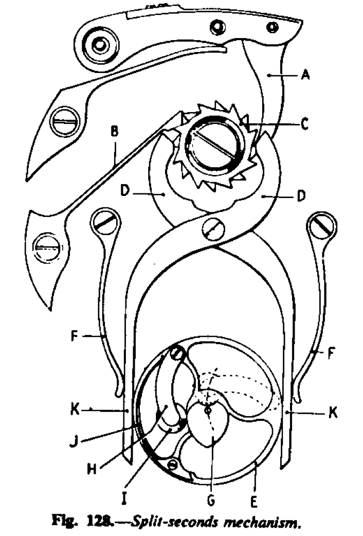
With the chronograph running and the split seconds wheel held firmly, the heart piece G will rotate and push the roller I away so that it will ride up and down upon the edge. If the -K jaws of the pincer-like levers are opened by reason of the teeth of the column wheel pushing them out, the wheel E will be released and free, and the lever H, pressing on to the heart piece, will be made to return to its zero position as shown by the dotted line outline of the lever and roller, which is at the base of the heart piece. Fitted to the wheel E is a long pipe and it is to this pipe the split seconds hand is fitted. When the split seconds wheel is free the chrono- graph and split seconds hands are together, i.e. one over the other, the split seconds hand below the chronograph hand. When the split wheel is gripped by the levers the split hand stops, while the chrono- graph hand goes on. With a movement of a lower grade, a lever somewhat similar to the return to zero lever is employed in place of the jewel roller. But whatever the alterations in design as a form of economy in production -the levers D may be two separate levers working one upon each side of the column wheel-the principle is as has been explained.
General Notes
The split seconds mechanism must be light in action and therefore it is delicate. No oil at all should be used on the split seconds wheels, i.e. on the pivots of the wheel, the roller, the lever or the heart piece; all these light moving parts should be left quite dry. To oil them would cause dragging. The column wheel, pivoting of the pincer-like levers, and where the spring impinges upon the levers should be oiled in the normal manner.
The fitting of the hands needs careful and close attention. First place the split hand on to its pipe in the exact zero position and then the chronograph hand also exactly in position. For the split seconds hands to be correct it should not be possible to see the split hand at all when viewing down upon the hands. In this instance the hands must not be “stroked” into position, as advised when dealing with the single chronograph. When the hands are viewed from the side, they should be perfectly parallel. The adjustment of the hands of a split second chronograph needs very careful attention indeed. It is work that cannot be hurried. It may be observed that the seconds chronograph hand appears to work forward after the chronograph action has been operated several times, this may be due to the hand itself not being hard enough, the return to zero is relatively violent and the sudden jerk jolts the hand and bends it, the temper of the hand is not good enough to straighten out. The remedy is to change the hand for one of better temper and more spring like.
Vintage rare chronograph watch parts