This crater deals with the automatically wound watch with a pedometer form of mechanism. Two types are in common use, one where the rotor makes a complete revolution and the other where the rotor through a segment of a circle and banks on each side upon bumper springs. Of the two systems the one where the rotor makes a complete rotation and winds in both directions is the best. The other system sometimes referred to as the “hammer” type cannot take the fullest advantage of every movement of the first of the wearer; further, the constant knocking of the rotor upon the bumper springs can be disturbing to the wearer.
There is little doubt that the automatic watch has come to stay, and the reason is not far to seek. First and foremost is that constant force is supplied by the mainspring during the hours when the watch is worn. Every horologist is conscious of the necessity of a “good action” (i.e., a good arc of vibration of the balance) especially in a watch worn on the wrist. Because of this, the error due to lack of isochronism of the balance is reduced. A good timekeeping rate cannot be expected if the action is poor. By “good rate” is meant a constant error in timekeeping; for instance, if the rate is, say, 30 seconds per week fast, the watch will not deviate more than a few seconds from the rate either way. It should not suddenly gain or lose, say, 15 seconds its rate. A watch may keep time to 60 seconds per week but during the week it may be:
+ 10 the first day
+ 30 the second day
+ 60 the third day
+ 80 the fourth day
+ 60 the fifth day
+ 40 the sixth day
+ 60 the seventh day
In this case the rotor is poor.
A good rate would be + 9 seconds each day. To obtain this condition a watch must reach certain standards-particularly, general good quality in finish, and correct adjustment of the train and the escapement, including the balance and spring. Thirdly, there must be an equal or almost equal torque of the mainspring at all times.
Winding a Watch
To obtain an almost equal torque of the mainspring, a fusee was introduced many years ago, but this practice is not only costly but cumbersome. The next best practice is to use automatic winding.
To obtain the best result from an ordinary winding watch it is necessary to wind it in the morning-or immediately before it is worn-these observations apply particularly to wrist watches. The reason for winding before wearing is to ensure that the balance shall have an arc of, say, 1 ¾ turns. Under these conditions the balance is less liable to be influenced by the movements of the wearer.
Tests have been made indicating that with the slipping mainspring used in animatic watches the torque may not be absolutely constant due to an erratic slipping of the mainspring. When the mainspring is fully wound it may slip back, say, half a turn and with continued use and consequent movement of the rotor, build up again to become fully wound, then slipping back, say, for three-quarters of a turn, and so on.
The variation of torque can, comparatively, be only slight and no doubt a device will be found to correct even this slight error. For instance, eight or more slight notches cut into the inside of the wall of the barrel will prevent a good deal of excessive slipping. But even so, taking the broad view, the automatic winding is still the best, and events have proved it to be so.
Good rates can be obtained with ordinary winding watches and if automatic winding is added to movements of the same size, extraordinarily good rates will be obtained. Manufacturers are inclined to use a small size movement for automatics, say, 9 ¾ ‘’ in a 12’’ case, to accommodate the automatic mechanism, but there is a trend to use larger movements. Eventually there will be the combination of a large movement and controlled slipping mainspring, which, with the progress already made with balance springs of low thermal error, should produce a watch with almost perfect rate.
Makers of Automatics
A trust, Ebauches S.A., has been formed in Switzerland of the Ebauche manufacturers, I.e., the factories which make the framework or major portion of the watch. Other factories make the escapement and there are factories which specialise in making deals, hands, cases, etc. Finally, there are the “finishers.” A “ finisher “ is the factory where the movement from the Ebauche factory is completed ; the plates, bridges, etc., are plated and finished; the movement is jewelled; escapement fitted; sprung and timed; dial and hands fitted and finally the movement cased. There are 17 Ebauche factories controlled by Ebauches S.A., but there are dozens of the finishing factories and each of the fishing factories gives the watch it finishes a name, a trade name, and an individuality of its own. In addition there are well over 100 factories in Switzerland that make their own Ebauche and finish the movements as well.
Ebauches S.A. factories make three automatic Ebauches which are sold to many finishers. The action and repair of these three models are described and also movements of the ‘complete factories’ are dealt with, so that if the reader comes across a movement with a name that is not among the “complete factory” list he will know that it is probably one of the Ebauches movements.
General Notes on Automatics
When winding the watch by the winding button, wind slowly. The automatic winding mechanism terminates in a train of wheel, which are sometimes small with fine pivots, and recently the wheels are thin and delicate, but quite strong enough for the purpose for which they are normally required. Winding the button vigorously places an undue strain upon these parts mentioned and damage may occur. Some movements are so designed that the train of wheels is not interfered with when winding by the button.
The cost to a manufacturer to tool up and produce a new calibre is enormous, and you may be sure every care has been taken in the design to ensure satisfaction of the finished article. A prototype is made, largely by hand, and thoroughly tested. Each part-wheels, pinions, levers, springs, screws, etc.-is carefully studied as it is in the factory’s interest to design and produce the best possible article.
Therefore, do not be temped to alter the design of any part. If you thing the fault lies in the malformation of a certain part procure a new piece from the factory that made the movement. It is not advisable to alter the shape of a part or even to repair a damaged part but to fit a new piece as supplied by the manufacturer. It is important to use the mainspring as supplied by the factory. Automatic winding mainsprings are fitted with a special slipping device and although there slipping ends may look simple to make they are not. They are made of a specially-hardened and tempered steel and formed to a required curve. Generally speaking, it is not advisable to remove the mainspring of it looks fresh and clean. Oil the automatic mechanism as indicated. Each manufacturer of the movements described has been approached and the oil and oiling instructions given are those recommended by the actual manufacturer.
About oil
A few words about oil will not be out of place. The viscosity of the oil used in an ordinary watch is important, but it is even more so when dealing with an automatic watch.
The Swiss recommend certain grades for particular parts and invariably they advise Chronic oil, made by Compagnie Francis de Raffinage, Paris, France. If this oil is not available an approximate equivalent may be obtained from the table following.
Ragosine watch and clock oils are manufactured by Recoil LTD., London and Leeds, and have been approved and recommended by Smith’s Clocks and Watches, Ltd., being used in all their products:
H.H.H. – Grade 300 (a heavy oil).
H. – Grade 180 (chronometers and clocks).
C. – Grade 120 (large watches and small clocks).
D. – Grade 120 (large watches and small clocks).
C.B.A. – Grade 60 (balance holes and escarpments of small watches).
Nowadays we recommend using Moebius oils and greases.
Grease
For lubricating same parts where a grease is required, activated and grease is recommended. Activated grease is a combination of mineral grease, I.e. petroleum jelly, with the addition of solid animal fat, e.g. stearine or stearic acid, to prevent spreading. Use nine parts petroleum jelly to one part animal fat, well mixed to a fairly stiff paste. The world “active” in this connection means it has non-spreading qualities. Generally speaking, animal (and vegetable, e.g. olive) oils have non-spreading properties, while mineral oils are deficient in that respect, hence an animal or vegetable oil tends to “stay put” while a mineral oil spreads until it dissipates itself away completely from the place where it was originally put. The activation can be achieved in two ways, one by treating the surface to be oiled (Epilame process) and the other by mixing the active substance (animal oil or stearic acid) with the oil. To summarise:
Epilame – A solution of stearic acid in toluene or carbon tetrachloride or other pure fat solvent. Benzine is not suitable owing to impurities which in course of time have a bad effect on the oil.
Activated (French “active”) treated to prevent spreading of oil or other lubricant.
Activated lubricant oil or grease containing animal oil or other active substance (e.g. stearic acid, olive oil, neat’s-foot oil, etc.).
Activated surfaces. – Surfaces of pivots, jewel holes, etc., which have been treated to prevent oil spreading.
Activated oils are usually petroleum oils to which a certain quantity of animal or vegetable oil has been added.
Activated grease. – Made from a petroleum base, e.g., petroleum jelly with the addition of a solid animal fat such as stearin or stearic acid, or an active oil such as neatsfoot or olive oil.
It might seem that animal or vegetable oil used alone would solve the watchmaker’s problems, but this is not practicable as both the types of oil tend to thicken quickly with age and are also subject to considerable thickening at low temperatures. There is one exception to this rule, the oil made by Kelley’s from the jaw of the porpoise.
Mineral oil is less likely to become thick with age, and another point in its favour is that, as it is less difficult to refine, its ultimate cost to the watchmaker is less.
The use of a correct oil for a particular purpose is important. If the parts of the automatic mechanism are not oiled with the correct oil the watch may not wind successfully.
Stoppers
When an automatic watch stops and it is not fitted with an “up-and-down” (reserve power) indicator, it is advisable to discover if it is the automatic mechanism or the watch movement which is at fault. If the movement is fitted with up-and-down work it will at once be seen that if the indicator points to fully wound it must be the watch movement that is at fault; on the other hand, if the indicator points to run down, then it must be the automatic work.
If no indicator mechanism is fitted, it is better to remove the automatic work (or part of it according to the type of movement) and apply the usual tests to the movement to ascertain if it is fully wound. Should it be fully wound, it will be apparent that the fault is with the movement; but should it not be wound, then fault is in the automatic work.
It is generally better to assemble the automatic mechanism on to the movement after the movement proper has been fully assembled, with dial and hands, and fitted into its case. When the automatic work has been fitted, apply the following test. (These remarks refer to all movements where a rotor is employed). Hold the watch, sight high, in a vertical position before the back of the case is in place and with the rotor facing you. Now turn the watch, still vertical, so that the rotor falls to the bottom. Keep turning the watch and the rotor should always remain at the bottom. Reverse the direction, and the rotor should still remain at the bottom. If it is found that the rotor lifts and is inclined to rotate with the watch then there is an obstruction. Examine carefully to find where the binding occurs and make the necessary adjustments.
Where bumper springs are employed apply the same test and rotate the watch so that the bumper spring on each side makes contact with the rotor. While this test is being carried out observe that the automatic mechanism is winding the watch.
It is of vital importance that the rotor should be absolutely free, so that the fullest advantage is taken of every movement of the wearer’s wrist while the watch is being worn.
The Mainspring
Special care must be give to the mainspring of all automatic winding watches. If ti is necessary to remove the mainspring because of thickened oil, clean it carefully with a piece of tissue paper dipped in benzine and draw the spring through a fold, keeping the same curvature of the spring. Do not attempt to straighten out the spring.
Clean the slipping spring device and, before replacing it in the barrel, use activated grease or graphite on the inside wall of the barrel to ensure a steady soft slipping. This is important because if the slipping is jerky it is inclined to let the mainspring slip too much and the amount of slipping controls the amount of force the spring exerts. If the spring slips too much, then the curve of the slipping piece must be fattened out. Conversely, if the spring winds up too tightly it is liable to cause the balance to knock the bankings, and the curve of the slipping piece must be more gentle.
The illustrations figs. 1 and 2 show the mainspring bridle incorrectly curved, not allowing the mainspring to be fully wound, and correctly curved. These illustrations are intended as a general guide and must not be taken as correct for all watches.
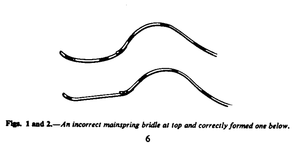
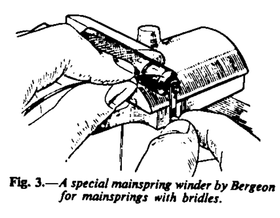
Fig. 3 is of a special winder for mainsprings with bridles, made by Bergeon. Practically all Swiss manufacturers recommend this winder.
Some manufacturers of automatic winding watches use the bridle as made and patented by Fabrique Suisse de Ressorts S.A. Fig. 4, the manufacturers of the Sirius mainspring. The springs, complete with bridle, are supplied in rings and it is advisable to push the spring into the barrel without removing the ring.
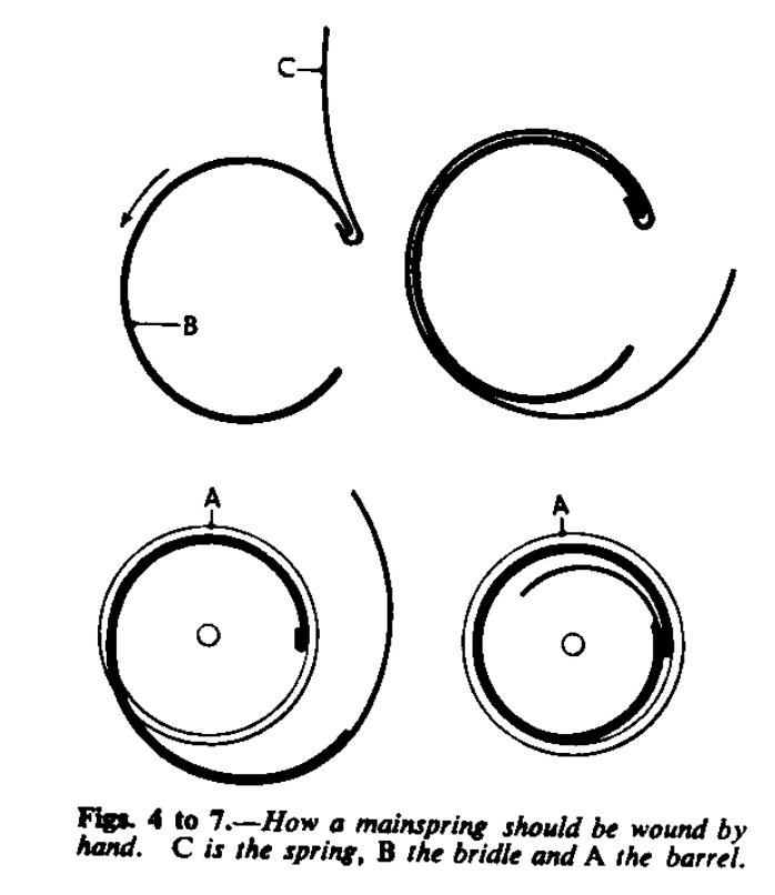
If, during repair, it has been necessary to remove the mainspring from the barrel it can be replaced by hand, as shown in the four illustrations Figs. 4 to 7. This method does prevent the risk of damaging the rim of the barrel. If possible, wind the mainspring and bridle into a ring and then present it to and push direct into the barrel. The inside diameter of the ring should be 0.20 to 0.30 mm. Larger than the inside diameter of the barrel.
BIDYNATOR (Ebauche, S.A.)
Feels S.A. Grenchen, Switzerland, make an automatic known as the Bidynator. The size o the movement is 11½’’ = 26 mm., calibre No. 690. The rotor traverses through 360°, winding in both directions and there is a centre seconds and. Fig. 8 shows the movement, and Fig. 9 shows it with the dial removed.
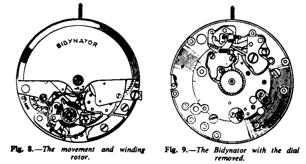
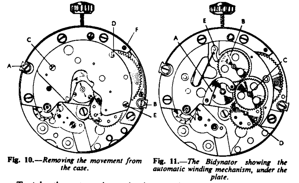
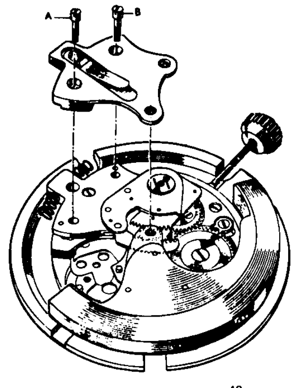
To remove the movement from its case, loosen the two screws, A and B (Fig. 10), and push back the small bolt pieces. Remove the winding shaft and lift the movement out of the case.
To take the automatic mechanism to pieces push down the small bolt piece (Fig. 8) to the left as shown by the arrow engraved on the rotor. Lift the rotor straight up, carefully, and away from the movement. It will be noted that there are two jewel holes in the rotor, one fitting on the lower part of the central post, and the other, a smaller hole, for the pivot at the top of the post. If any undue side pressure is brought to bear on the central post while removing the rotor there is a risk of breaking one or both jewel holes, so lift the rotor straight up. It is not necessary to remove the rotor fixing bolt position to minimise the risk of the spring jumping out.
Replace the winding shaft and let the mainspring down by holding back the click, which has a slot cut in its upper pivot, F (fig. 10). Now remove the three screws, C, D and E (Fig. 10), and lift of the plate, which is the top plate of the automatic work. This will expose the mechanism as shown in Fig.11.
The action is as follows: The steel wheel fixed to the rotor gears into the small steel wheel which is riveted to the rocking arm, A (fig.11), and as the rotor moves, say, to the left, it gears into the steel wheel B, and if to the right, into the steel wheel C, so that as the rotor rotates either to the left or right the wheel C rotates in a clock-wise direction. The wheel C has riveted to it a pinion which gears into the wheel D and this last wheel has a ratchet device fitted to a pinion which gears into the main ratchet wheel of the watch movement. If the watch is wound by the winding button the ratchet attached to the pinion of the wheel D rotates backwards so that the train of the automatic mechanism is not reversed.
The click E (fig. 11) holds the mainspring up during even a small movement of the rotor until sufficient movement has been obtained for the click of the main ratchet wheel to take over. Furthermore, the click E prevents the train from reversing while the strength of the click spring in the wheel D has been overcome during the process of winding by the button.
Except for the wheel fixed to the rotor, the whole of the automatic work can be taken to pieces for purposes of cleaning. If the rotor needs adjustment because there is too much freedom and a risk of it touching either the inside of the back of the case or the top plate of the movement or there is lack of freedom, thus endangering the winding, it can be corrected by lowering the top jewel hole of the rotor to correct the former fault and by raising it to correct the latter. In either instance it will be necessary to push the hole out and reset it to the required height.
Cut a piece of peg wood so that it fits into the lower hole fairly tightly, then cut the end square so that it will press on the under side of the top jewel hole. Hold the rotor on the pad of the thumb of the left hand and with the peg-wood in the right hand slowly and firmly push the top hole out. To rest, use the friction jewel setting tool.
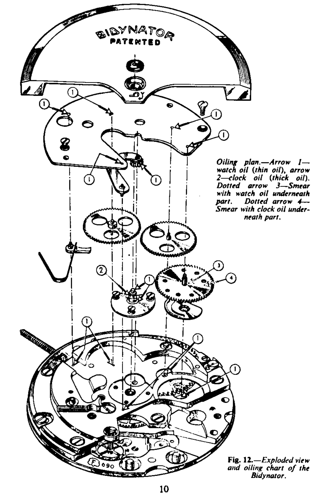
Having cleaned the whole of the movement, reassemble and oil as indicated in the chart (Fig. 12).
BOVIMATIC
A pin pallet automatic watch is made by Baumgartner Freres S.A. Grenchen Switzerland. Known as the Bovimatic B.F.9 cal. 92 (Fig. 13), it has a very simple and cleverly designed movement. The rotor rotates through a segment of a circle and winds in both directions.
The action is as follows: Fitted to the underside of the rotor is a pin A (Fig. 13), which contacts the plate B, in to which is fitted a click engaging a ratchet wheel. Another click, C, attached to the movement also engages into the same ratchet wheel, D. As the rotor revolves to the right the pin in the rotor contacts the plate at A in Fig. 14 and pushes it round. The click carried on the plate causes the ratchet wheel to rotate. Fixed to the ratchet wheel is a pinion which gears direct into the main ratchet wheel of the watch. The click fitted on to the movement holds the mainspring up in position and also acts as the mainspring click. The advantage of this is that the teeth of the ratchet-shaped tooth wheel are fine and in this simple manner the fullest advantage is taken of all movement of the rotor.
The spring B (Fig. 14), fitted to the plate, causes it to fly back to its normal position so that the click fitted to the place idles over the teeth.
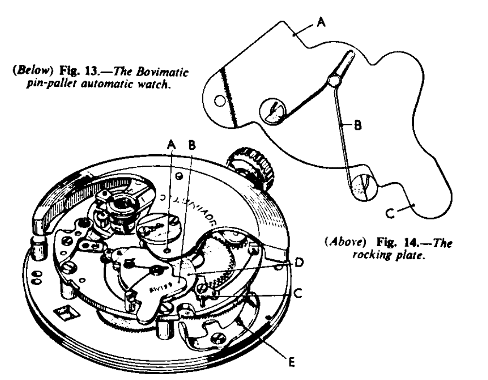
As the rotor revolves to the left, the end of the rotor itself contacts the plate at C (Fig.14) and causes it to rotate so that the click again pushes the ratchet wheel round in the same direction, and the click on the movement retains the number of teeth the gathering click has gathered up.
A strong and simple buffer spring stop E (Fig.13) controls the movement of the rotor. The rotor requires a fairly violent shock to cause it to operate but under test in wear it has proved quite satisfactory. Owing to the necessity of this shock to wind, the normal tests as noted on page 5 issue cannot here applied.
BULOVA
The Bulova movements are made by the Bulova Watch Co. Of America. There are three models; 10 BPAC and 10 BOAC both with 23 jewels are made in the American factory of Bulova, and 10 CBAC with 17 jewels is made in there Swiss factory. All three models function exactly similarly and the parts are almost completely interchangeable.
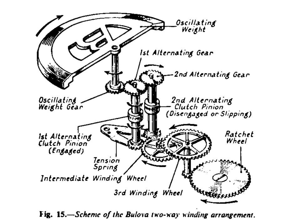
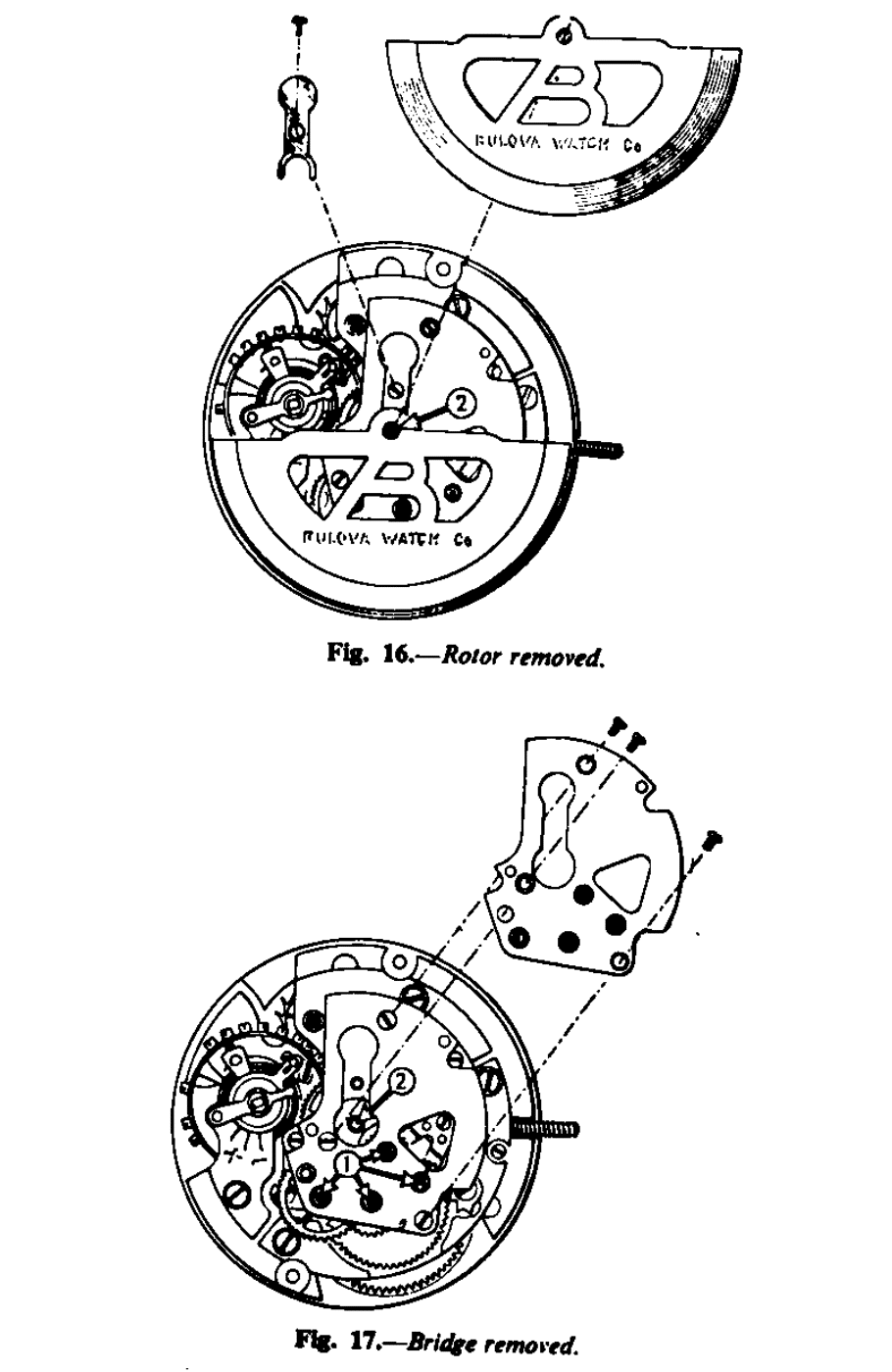
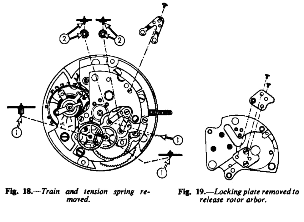
The rotor traverses 360° and winds in both directions. Fig. 1 is an exploded view of the automatic winding mechanism and the unique feature is the two crown and castle-like wheels or alternating clutch pinions. To dismantle, remove the plate, shown in Fig. 16, and lift the rotor up and away from the movement. Then remove the bridge as shown in Fig. 17. Remove the train and tension spring as Fig. 18. The rotor arbor is removed from the automatic winding bridge by taking off the plate under the bridge, Fig. 19. The movement can now be taken apart in the conventional manner and cleaned.
To re-assemble; assemble the movement up to the automatic work and then proceed in reverse order to that given above. The design is simple and straightforward. The oiling, as recommended by Bulova is as indicated by the arrows in Figs. 16, 17 and 18. 1, clock oil; 2, grease, such as an activated grease.
ELGIN
The Elgin automatic is made by Elgin National Watch Co., Elgin, Illinois, U.S.A.
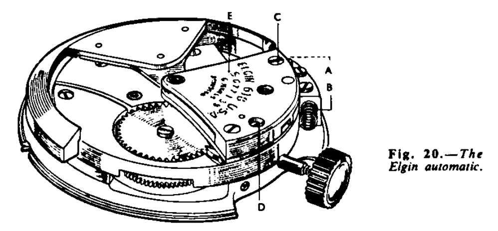
The action of this automatic winding (fig. 20) is extremely simple. The rotor moves through a segment of a circle, and buffer springs are employed. Attached to the rotor is a segment of a gear which engages another gear segment cut on the end of a rocking arm. Fitted to this rocking arm is a steel ratchet wheel with a pinion fixed to it.
The pinion gears directly with the transmission wheel of the keyless mechanism; a click and spring is fitted to the rocking arm and another and similar click and spring is fitted to the fixed bridge of the auto-wind work. As the rotor oscillates from side to side the rocking arm is caused to move from side to side also, and, by virtue of the click fitted to the arm, the ratchet wheel is made to rotate in one direction. The other small click holds the ratchet in position until the click of the main ratchet wheel takes over.
To dismantle: First remove the two buffer springs, A and B (Fig. 20), then the two screws C and D, holding the bridge of the automatic work E. The whole of the automatic mechanism can then be lifted off.
Place the automatic work flat on the bench upside down and remove the screw A (Fig.21). The rocking arm B can then be removed and also the click C. It is not necessary to remove the gear segment from the rotor. Remove the three screws of the plate holding the ratchet wheel on the rocking arm and remove the click.
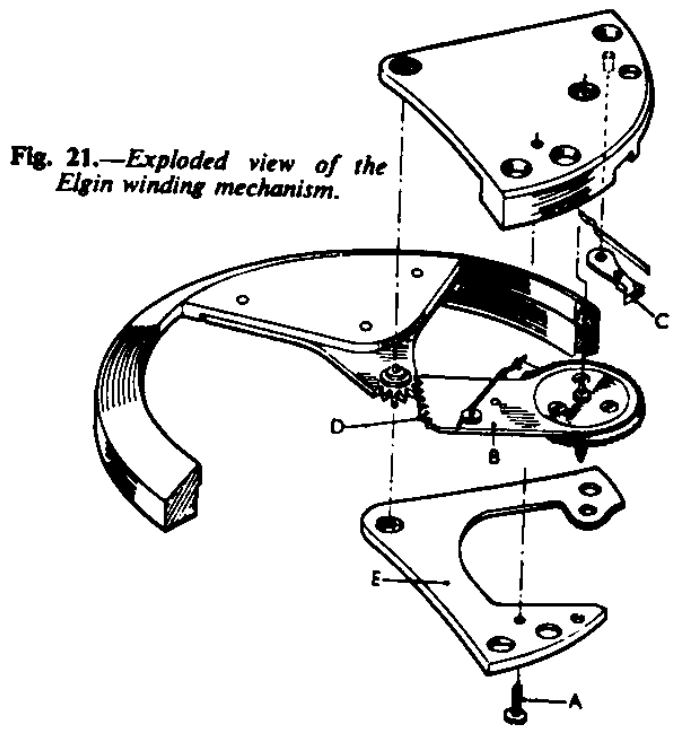
After cleaning, re-assemble in the following manner: First, the rocking arm-apply a little watch oil to the seating of the ratchet wheel and also to the seating on the plate, then replace the three screws.
It is of vital importance that this wheel be perfectly free. Replace the click and apply watch oil to the shoulder of the click screw, then fit the click spring. With the bridge E, upside down on the bench, please the rotor and the rocking arm in position so that the end tooth of the rocking arm rack engages in the end space of the rotor rack, as D. See that the click fitted to the bridge E engages wit the ratchet wheel; then screw this bridge E into position. Oil the lower pivot of the rotor sparingly with watch oil and also oil the lower pivot hole of the rocking arm. Fit the winding stem into the movement. Hold the whole of the automatic assembly firmly with the tweezers and place in position on the barrel bridge.
If the pinion of the rocking arm does not gear immediately with the transmission wheel of the keyless work, just turn the winding button slightly to bring the transmission wheel into its correct position.
Finally, replace the two screws to hold the auto-wind mechanism in position. Oil the upper rotor pivot sparingly with watch oil. The rotor should have no end-shake between its jewel holes, but it must be perfectly free.
ETAROTOR (Ebaches S.A.)
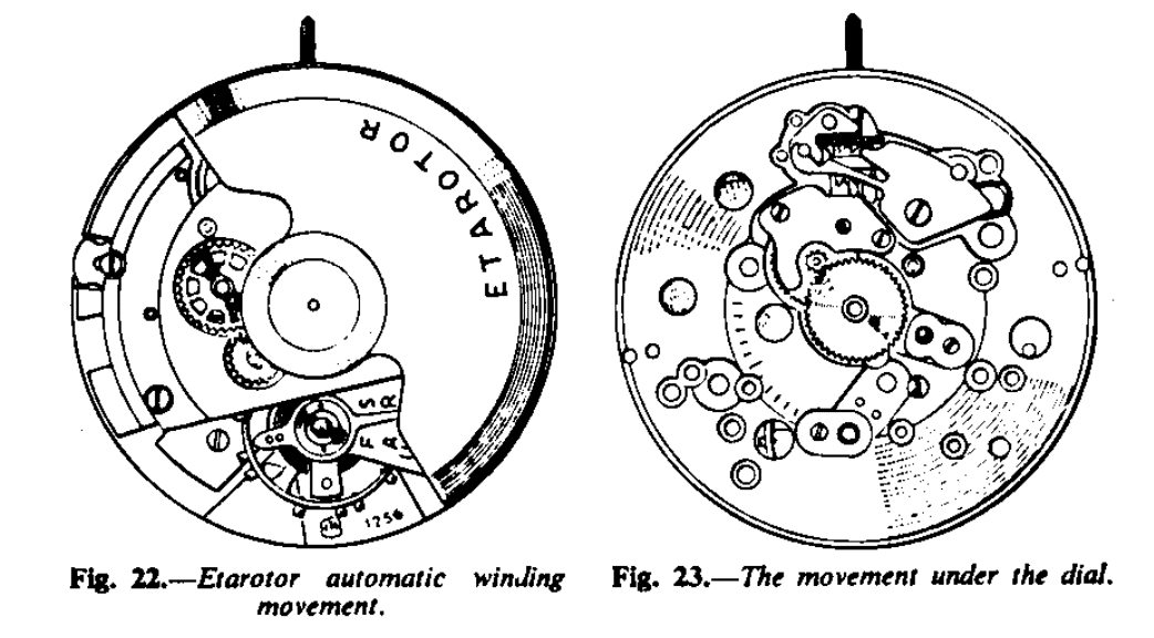
The next movement is one of which the Ebauche is made by Eta S.A. of Grenchen, Switzerland. Figs.22 and 23 show two views of the movement, one with the dial removed. The name given by the Ebauche maker is Etarotor. The size of the movement is 11½’’’ = 25.6 mm., and the calibre number is 1256. The rotor traverses 360° and it winds the mainspring in both directions. A centre seconds hand is fitted.
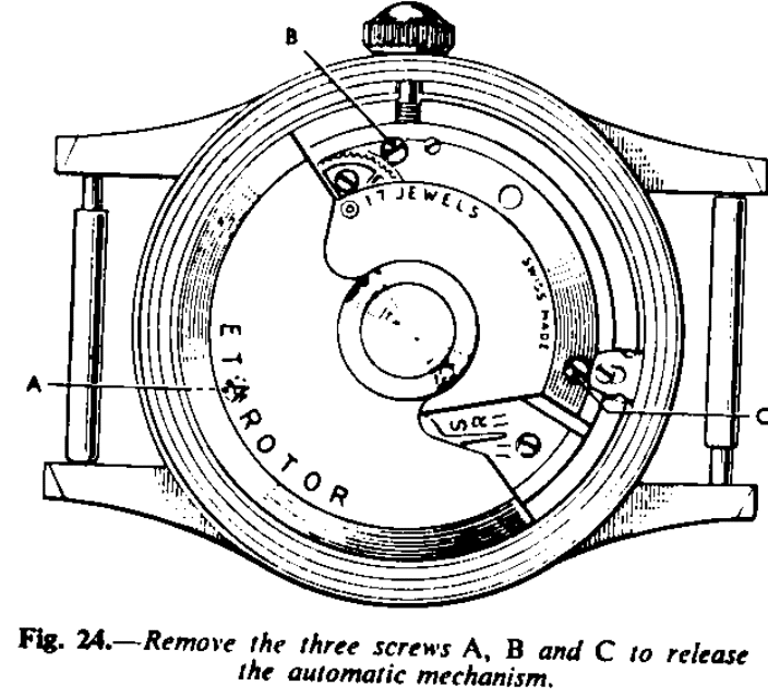
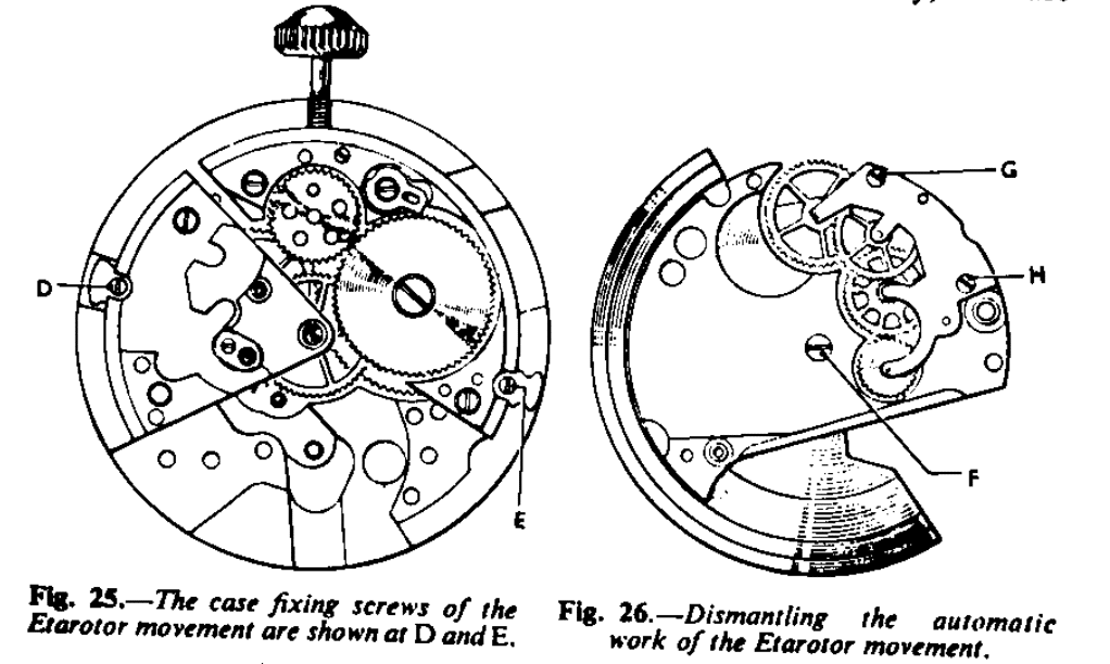
The movement is removed from its case by first unscrewing the three screws, A, B, and C and removing the automatic device (Fig. 24). This will release the whole of the automatic mechanism. Then remove the winding button and shaft and finally unscrew the two screws, D and E (fig. 25) had a turn and the movement can be taken from the case.
The automatic work operates in the following manner. Fixed to the rotor is a steel wheel, A (Fig. 26) which gears into two other steel wheels B and C. Wheel C is the reverser wheel and consists of two steel wheels with a plate between them; they are riveted to a pinion so that the two wheels are free but the plate is fixed to the pinion. On each side of the plate is a small free spring with one end turned up to intercept the arms of the wheels and form a system of click work. The wheel on the rotor gears into one of these wheels and also, as mentioned, into another wheel. Fixed to this last-mentioned wheel, B, is another wheel, D, with a steel bar between them and the effect of turning the rotor one way of the other is to cause the plate with the clicks between the two wheels (the reverser) to rotate in one direction only, because when one wheel is free-wheeling the other is driving and upon reversing the direction of the rotor the other wheel is driving and the first wheel is free-wheeling.
The pinion of the reverser wheel attached to the click plate gears into the wheel E, which in turn gears into another wheel and pinion, F, which gears into the transmission wheel, G, of the ordinary keyless work, and so winds the mainspring.
During repair the reserver wheel is not taken to pieces and neither are the two wheels B and D riveted to the bar.
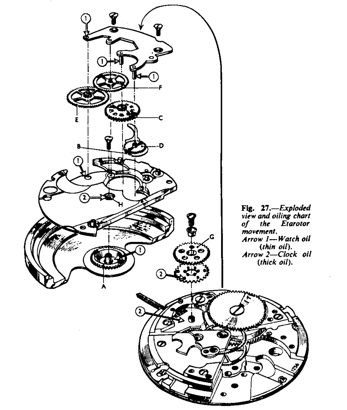
To take the automatic work to pieces, unscrew the screw F (Fig. 26) which will release the rotor, and then screws G and H. Lift off the bridge over the reduction gears, winding pawl and the reverser. The rest of the movement is then taken to pieces and cleaned as explained in other article. The automatic work is cleaned and similar manner.
Having fully assembled the movement and oiled all the pivot holes in the top plate, fit the movement into the case and proceed to assemble the automatic work. Place the automatic plate on the bench and assemble the wheels. It is not necessary to oil the plate between the reverser wheels or the click work; it is essential to leave this perfectly dry. Give both sides several hard puffs with the bellows to ensure freedom from dust. See oiling chart (Fig. 27) for particulars of oiling and then reassemble the automatic work on the movement.
If the rotor, through wear, has too much up-and-down shake, it can be reduced in the following manner: Reduce the length of the core H (Fig. 27) with a cutter made by whetting the end of an old round file to a pyramid shape at an angle of 60°. Cut very little away at first and try the rotor on position. If the rotor is too tight, adjust the core by raising ti a trifle; place the plate with the core over a hole in a stake and with a small, flat-faced punch, a little smaller than the outside diameter of the core, tap the core up a trifle.
The fitting of the rotor is rather critical; if it is loose it is liable to rub on the inside of the back of the case, which could cause incorrect operation. On the other hand, if it is too tight it may not operate at all or, if it does move when the watch is worn, it may not move sufficiently to enable the automatic mechanism to wind the mainspring up fully. It is worth spending some tome to ensure that the rotor is accurately free.
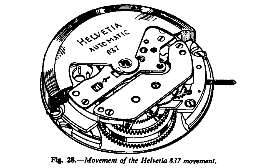
HELVETIA 837
The Helvetia 837, made by Helvetia Watches, LTD., Bienne, Switzerland, has and 11½ movement with centre seconds hand or with off-set seconds hand. The rotor revolves through an arc of 360° and winds the mainspring in one direction only.
The action is as follows: fixed to the rotor is a steel pinion which gears into a steel wheel controlled by a pivoted click, so that this wheel can rotate in one direction only. The underside of this wheel has ratchet teeth cut into it and it fits freely on the arbor of another steel wheel, which also has teeth cut into its upper surface, similar to the first wheel mentioned. The two wheels are kept in contact by a spring.
The action is similar to that of the crow and castle wheels of the conventional keyless mechanism which is known as the Breguet ratchet work. The upper wheel therefore drives the lower wheel in one direction, which in turn gears into another steel wheel with pinion attached, and it is the pinion of the last wheel which gears into a ratchet wheel through a click, driving the ratchet wheel of the mainspring and so winding it up.
When it is required to wind the mainspring manually, two small wheels, which constitute the transmission, come into action. One is pivoted to a s small racking bar, and as the winding button is turned anti-clockwise this wheel is thrown into the lower ratchet wheel, which is the main ratchet wheel and winds the mainspring. Thus during manual winding, the automatic mechanism is not connected at all, and it is necessary to turn the winding button in the reverse direction to the conventional forward direction to wind the mainspring.
To dismantle: withdraw the bolt as indicated by the arrow, and the rotor can be shake off while holding the bolt back and turning the movement to one side. Hold back the check click A (Fig. 29), so as to release the automatic train and for the main ratchet click to the the power of the mainspring. Remove the two screws B and C and lift of the bridge D, the spring E, the click A and also the wheels F and G. The wheel F is the double ratchet wheel already mentioned. The remove the screws H and I and the bridge J. Remove the wheel K and the barrel arbor L and the top ratchet wheel with its click and spring, then the ratchet wheel M and finally the wheel N, and the barrel will slide out from the movement.
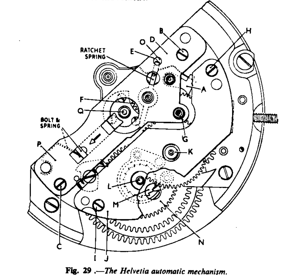
Having cleaned the movement and assembled up to the escapement, but not the barrel, start to re-assemble the automatic work. Slide the barrel into position with the steel wheel, then place the ratchet wheel on the barrel arbor square with the dot marked on it upper-most. Place the ratchet wheel with the click and spring attached over the wheel M. First oil with clock oil the click and the spring where it impinges on the click. Now place in position the loose barrel arbor, oiling its bearings first. Oil with watch oil the lower hole of the wheel K and place this wheel in position. Replace and screw up the bridge J. Oil with watch oil the lower hole of the wheel F and G, and apply clock oil to the ratchet teeth between the two wheels of F. Place this wheel and the wheel G in position, and also the click A and then the spring E. See that the turn-up end is uppermost and in position so that the turn-up end will enter into the hole O. Apply a little watch under the spring first. The bolt ad its spring can be placed into position later.
Now replace the bridge P. Unscrew the screw C and lift up the end of the bridge P to allow the spring and bolt to be slipped under and into position, and then screw down the bridge.
Apply clock oil to the post Q, and also to the groove above the wheel fixed to the rotor. Hold the bolt back as indicated by the arrow, place the rotor into position and release the bolt. Oil with watch oil the top pivots of the automatic train.
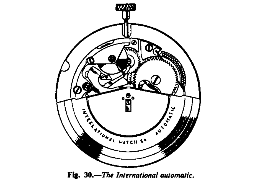
INTERNATIONAL WATCH CO
The rotor of the International automatic movement, made by the International Watch Company, Schaffhausen, Switzerland, revolves the complete circle and winds in both directions, Fig. 30.
The action is as follows: Fixed to the rotor is the heart-piece A, Fig. 31, and as the rotor rotates, it moves the rocking arm B, which is pivoted at C, through the two rollers D and E. The rocking arm consists of two plates and the rollers and the two clicks F and G are pivoted between the plates. As the rotor moves to the right the heart-piece in turn moves the roller E upwards, and the click G idles over the ratchet teeth of the wheel H. At the same time the click F draws the wheel H round to the left. Conversely, as the rotor moves to the left, it moves the rocking arm downwards and the click F then idles and the click G draws the wheel H to the left. Fixed to the wheel H is a pinion which gears into the transmission wheel of the watch movement and so winds the mainspring.
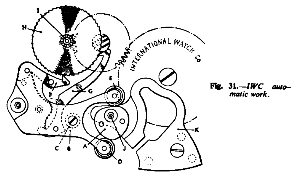
It is a simple and most ingenious system, well constructed and beautifully finished.
The rotor is pivoted on to the post J which is fixed to the substantial shock-absorbing spring K. The mainspring is the slipping variety, employing the system as illustrated in Figs. 4 to 7.
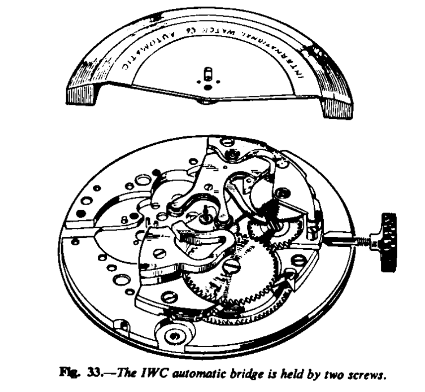
To dismantle, first remove the rotor. To do this, unscrew the screw in the centre half a turn and pull back the small bolt-piece. The rotor can then be lifted off.
The tension of the mainspring held by the clicks is relived by pressing the click A (Fig. 32) back until it is locked in the notch B of the click C. This movement disengages the click C from the wheel D.
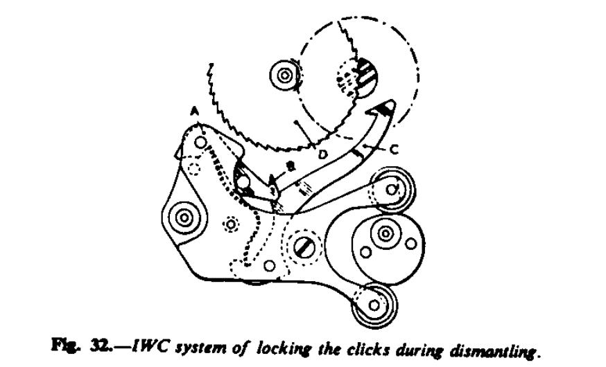
The full power of the mainspring is then let down in the conventional manner by holding the winding button and withdrawing the click from the main ratchet wheel. This system is useful when fitting a new mainspring. It is then only necessary to remove the rotor and its support K (Fig. 31).
To proceed with the dismantling, remove the two screws holding the automatic mechanism bridge. The ratchet-toothed wheel and the rocking arm can them be removed. Next, remove the rotor support. The rocking arm assembly is dismantled by removing the screw holding the upper plate. It is not necessary to remove the heart piece from the rotor.
Re-assembly
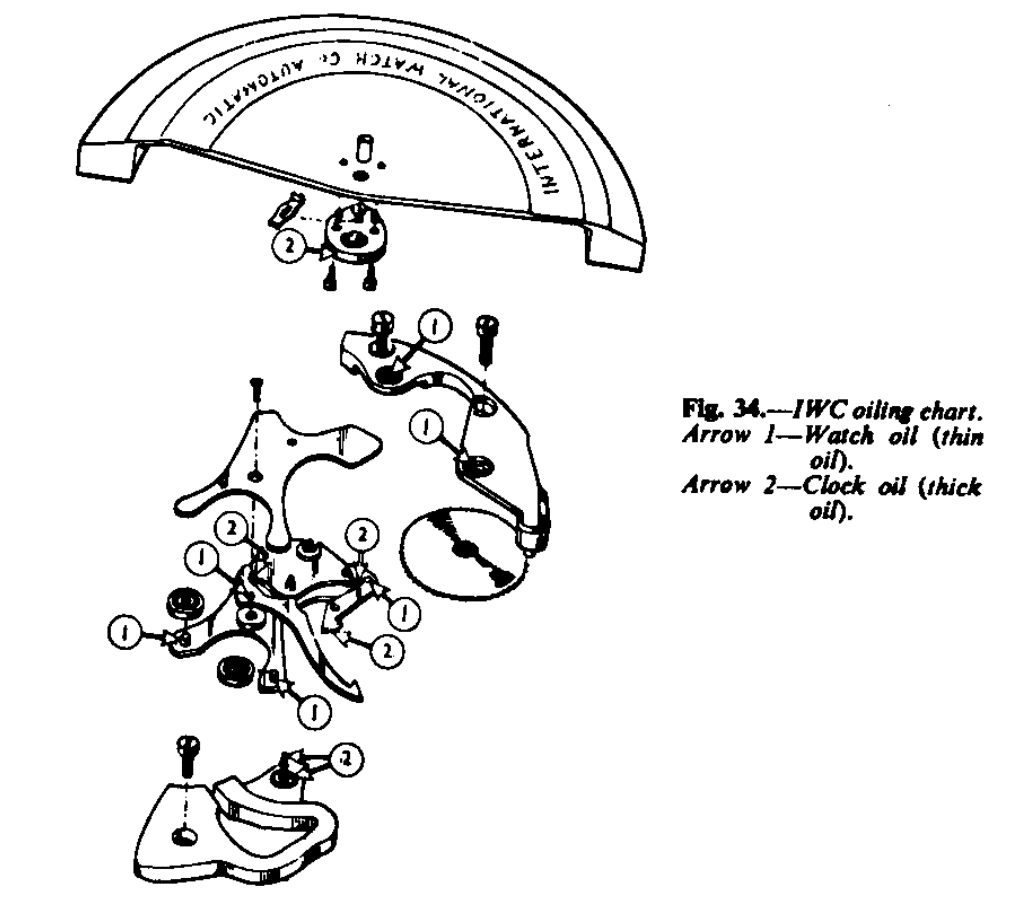
Clean the movement and assemble it ip to the automatic work. Having cleaned the parts of the automatic work, assemble as follows: Re-assemble the rocking arm and oil the bearings of the rollers and the clicks and also the points where the spring of the clicks contacts the clicks with very little clock oil before replacing the upper plate. Apply clock oil to the lower pivot holes of the ratchet-toothed wheel and the rocking arm. Replace the rotor post spring. Apply clock oil very sparingly to the levers of the ratchet-toothed wheel and then place this wheel and the rocking arm assembly in position, and finally screw on the automatic mechanism bridge. Oil the top pivots of the ratchet-toothed wheel and the rocking arm. With clock oil, oil the post for the rotor and screw the rotor back into position. Apply very little clock oil to the nose of both clicks operating on the ratchet-toothed wheel and just smear to the edge of the heart-piece of the rotor. The oiling chart is shown in Fig. 34.
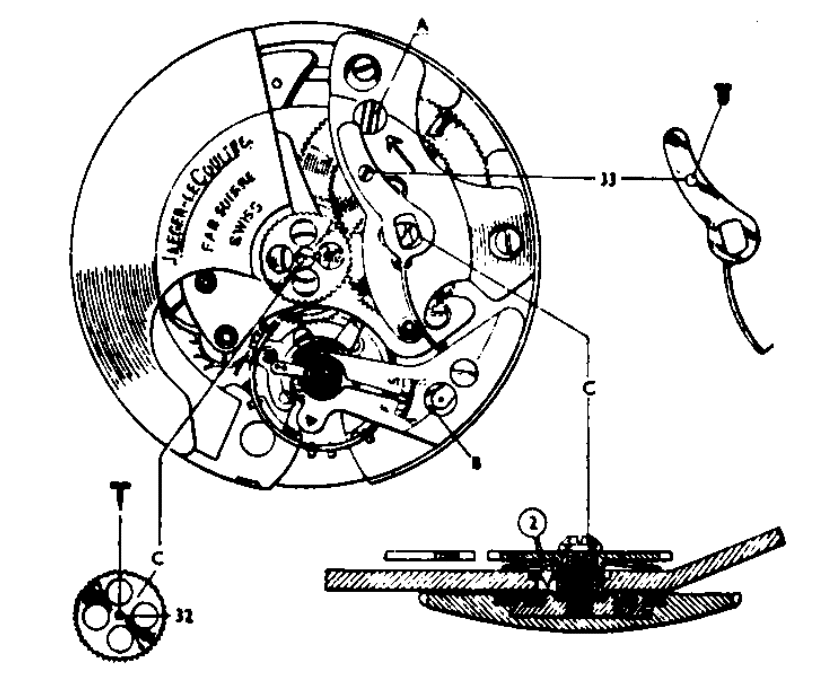
LeCoultre
LeCoultre, of Le Sentier, Switzerland, make three models of automatic-winding watches: Calibres 497, 476, and 481. Cal. 481 and 476 employ similar automatic mechanism. Cal 497 is the latest model and the one described.
The movement of cal. 497 is a departure from the conventional automatic-winding watch inasmuch as the rotor is arrested when the mainspring is fully wound and the slipping mainspring device is not necessary. No provision is made to wind the watch manually; a few shakes of the watch are sufficient to start the balance vibrating at a good amplitude: since the mainspring is set up before winding starts, it is virtually fitted with stop work. It is interesting to note that this system is, fundamentally, the same as that employed by Recordon, who was granted a patent in 1780 in England.
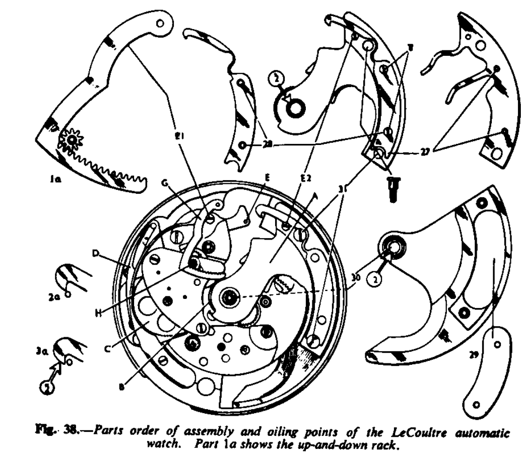
The rotor operates through a segment of a circle and winds in both directions. The buffer springs are shown in Fig. 38, No. 27.
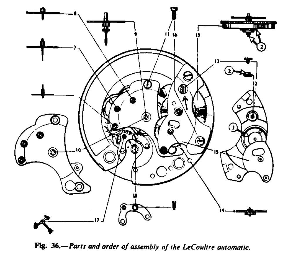
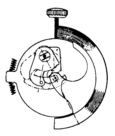
The movement is 12’’ and a 12’’ escapement is employed. The action is as follows: Screwed to the under-side of the rotor is the plate A (Fig. 38), which has fixed to it the steel wheel B. This wheel, with another wheel of similar size, is pivoted on to a small rocking arm, and, as the rotor moves backward and forward, one or other of these two wheels is made to gear into the wheel C, which has ratchet-shaped teeth. As wheel C is made to rotate it is help up by the click and spring combined D. It is this click which holds up the mainspring; there is no click work associated with the main ratchet wheel.
Fixed to the wheel C is a pinion gearing into the transmission wheel, which in turn, through a pinion, gears into the ratchet wheel to wind the mainspring.
The barrel arbor has a long left-hand thread, on to which is screwed a disc. Two long-headed screws are screwed into the barrel cover and the disc, which has holes drilled into it, and is able to rise as the barrel arbor is turned during winding and to fall ass the barrel rotates, because the two screws already mentioned will cause the disc rotate.
Attached to the lier E (Fig. 66) is a cone-shaped stud, and this stud is made to bear upon the periphery of the steel disc: therefore, as the disc rises it pushers the lever to one side, and when the disc has reached its highest position, I.e. when the mainspring is fully wound, the pin on the lever E will contact the hook (Fig. 38).
This spring hook is fixed to the under plate of the rotor, and therefore the rotor is arrested. As the disc is lowered by the running of the watch, so the pin disengages the hook and the rotor is then free to rotate-an ingenious device which is in principle the same as that employed in the earliest automatic-winding watches already mentioned.
Up-and-Down Work
The rack G (Fig. 38) is controlled by the lever E, and this gears into the pinion H which is fitted with a pipe on to which the up-and-down hand is fitted.
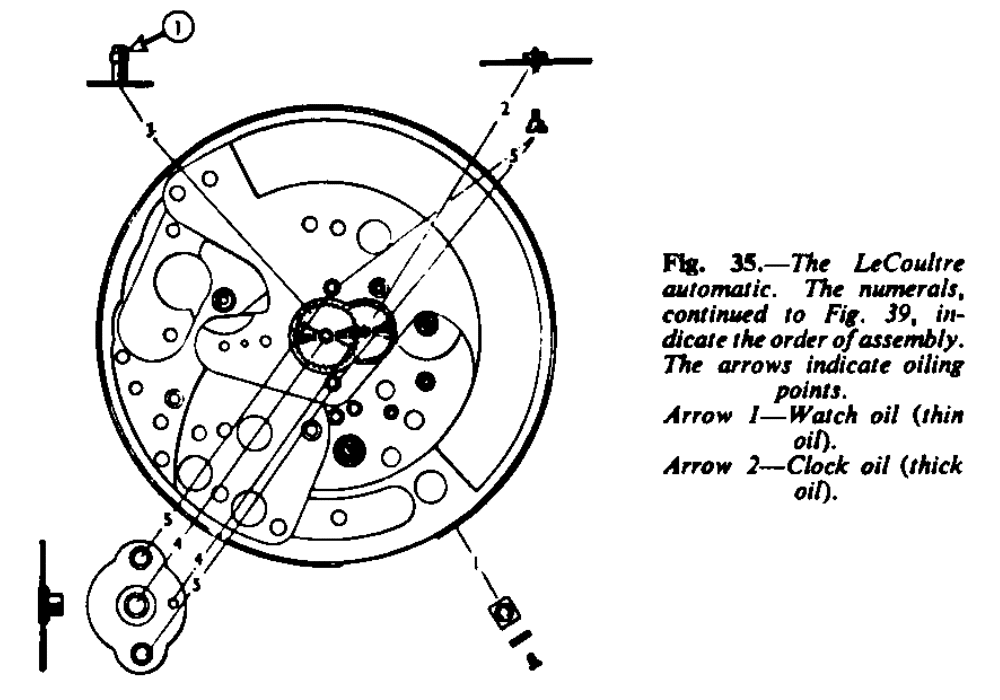
This watch seems a little more complicated than some automatic watches, but it I, in fact, quite simple. Care is needed in dismantling and assembling, and LeCoultre suggest the order as numbered in Figs. 35 to 39.
To Dismantle
These instructions apply only to dismantling and assembling the automatic work. First let down the power of the mainspring. The screw A (Fig. 39) has fixed to it a small wheel which gears with the ratchet wheel. The sole purpose of this wheel is not let down the mainspring. There is no winding shaft.
Place the properly-shaped blade of a screwdriver in the slot and carefully and firmly turn clockwise, at the same time holding back the click, through the hole B (Fig. 39). Then slowly let the screwdriver revolve to let down the spring (4 turns of the screw = 1 turn of the barrel arbor). N.B.: The screw A and the thread of the barrel arbor for the disc are left hand.
The numbers (not those in circles) given in Figs. 35 to 39 indicate the order of assembly, therefore, to dismantle, start at the last number 33. The two screws marked E1 and E2 (Fig. 38) are eccentric screws and should not be touched. They are used for the adjustment of the up-and-down work and for the correct position for the arresting hook of the rotor.
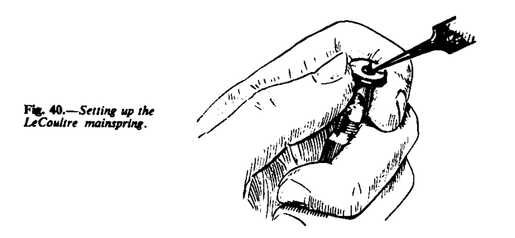
Having taken the movement to pieces, next deal with the barrel. Holding the barrel arbor by its square, in the pin tongs, wind up the mainspring a fraction of a turn and hold the barrel; then remove the two screws holding of the disc and unscrew the disc-left hand thread. The barrel, etc., is cleaned in the conventional manner.
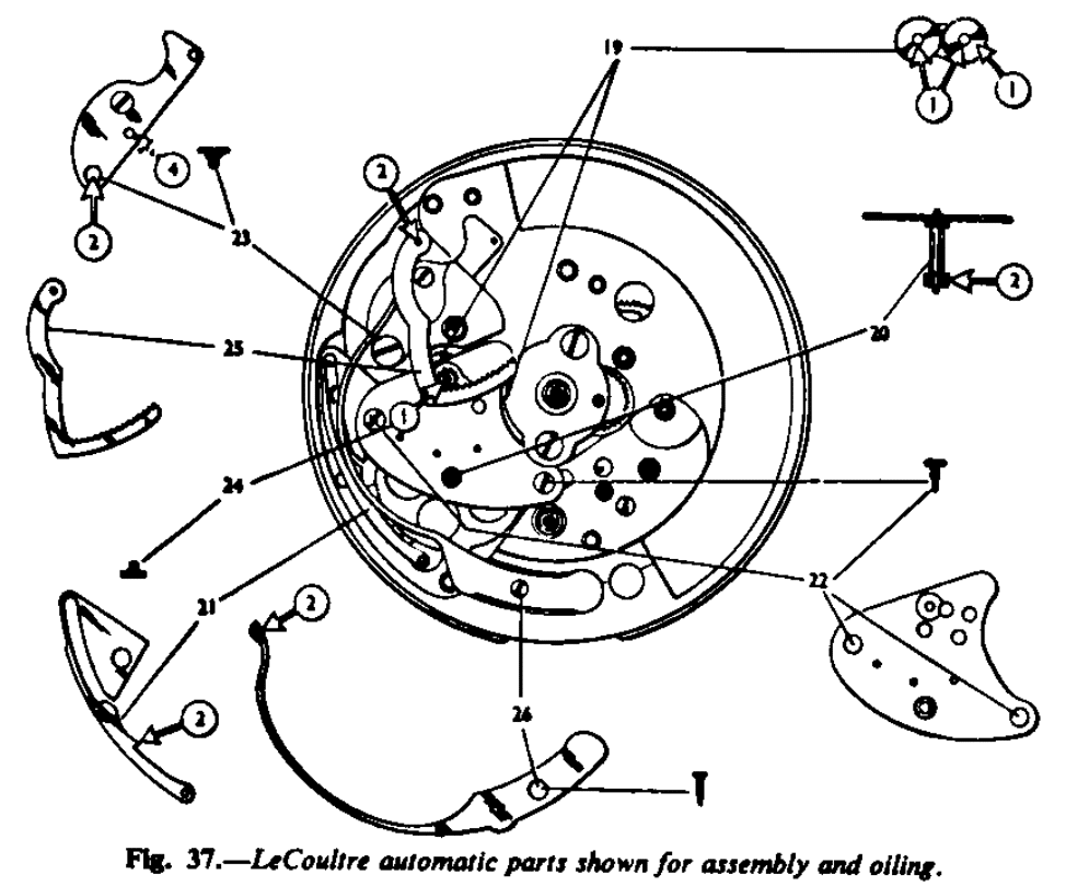
To assemble the barrel, hold the arbor in the pin tongs as before and wind the mainspring up to 1 to 1¼ turns, screw the disc hard on to the arbor, and replace the two screws (Fig. 40). The mainspring is thus set up. Having cleaned the movement and assembled up to number 18 (Fig. 36), proceed to assemble the automatic work as Figs. 37 to 39. Oiling points other than pivots are noted in the illustrations by numbers in circles. Oil with moderation. The pivots are oiled in the conventional manner with watch oil.
Having assembled the movement, the adjustments to observe are: With the mainspring run down (to the limit of the stop work), see that the up-and-down rack is in the position shown in 1a (Fig. 38), I.e. just resting on the eccentric screw-head, allowing the pinion for the up-and-down hand to be placed in position. Next, wind the mainspring up three turns (12 turns of the screw A, Fig. 39), and the hook of the rotor should be as 2a (Fig. 38) with relation to the pin, that is to say, it should just pass the pin. Wind the screw A (Fig. 39) four more turns (1 turn of the barrel arbor) and the hook should engage the pin as the figure under 2a (Fig. 38). Make sure the hold is secure so that a sudden shock will not release the rotor.
The up-and-down hand is placed in the zero position when the mainspring is down.
The hands are set by sliding the button on the back of the case to one side: towards the centre of the case to set the hands and towards the edge of the case for the neutral position. When this button is moved to the hands set position the lever into which the head of wheel C fits is mode to stop the balance.
The wheel C (Fig.39) is for the purpose of setting the hands.
LEMANIA
Made by Lemania Lurgin, S.A. Orient, Switzerland, the Lemania movement is 12 line in size. The calibre number is 3,600. The rotor oscillates 360°, winding in one direction only. Fig. 41 show the movement.
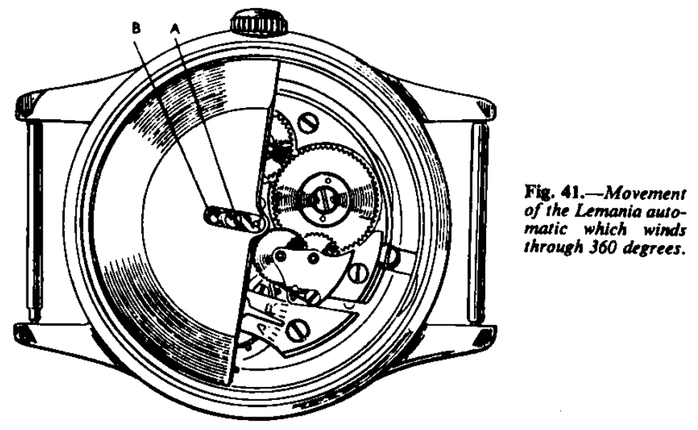
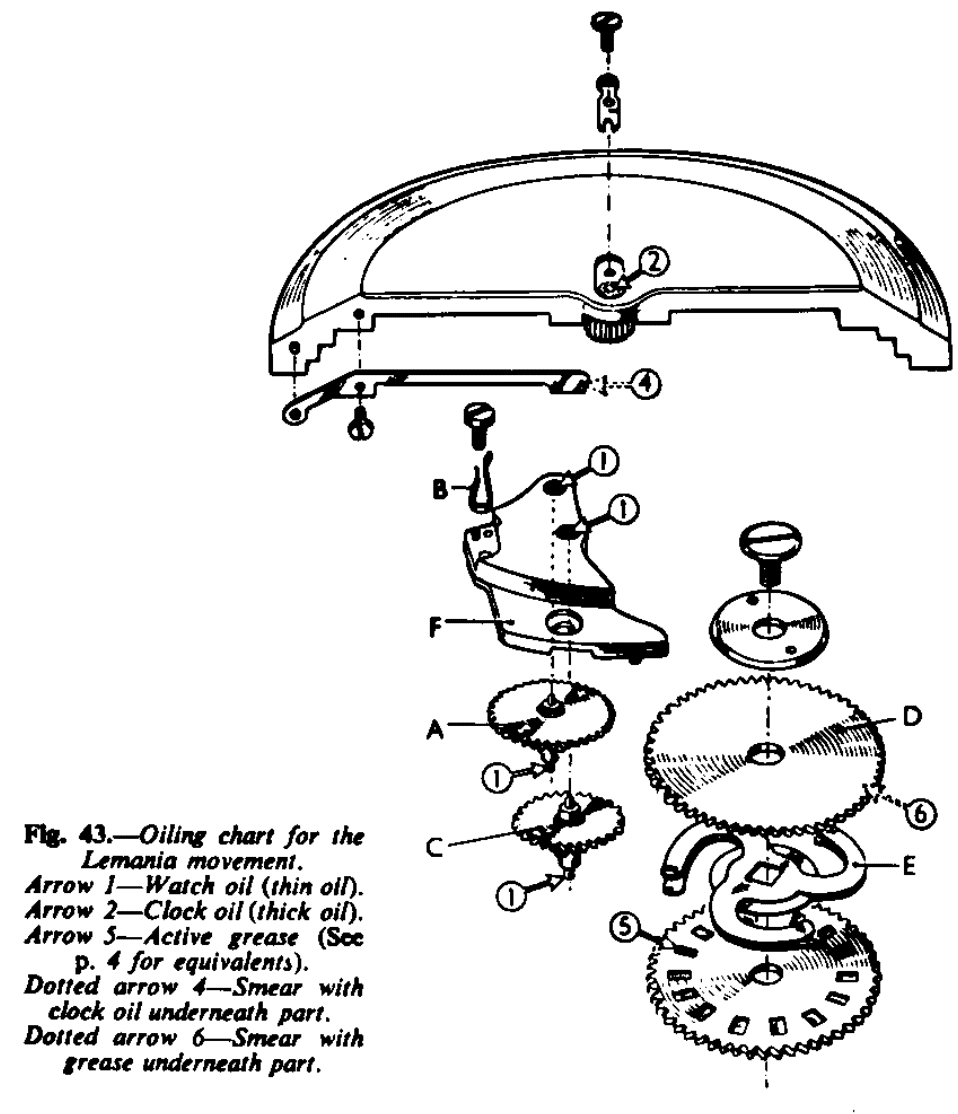
The action is follows: The rotor has fitted to it a steel pinion which is free to rotate, a long side click and spring combined allows it to revolve in one direction only and it is this spring which conveys the driving force to wind the mainspring. This pinion gears into a brass wheel A (Fig. 42), which is controlled by a wire click B; this wheel has a pinion attached to it which in turn gears into another wheel C. The wheel C has a pinion attached to it which gears into the upper of two ratchet wheels of exactly the same size D. Both the upper and lower ratchet wheels have round holes. The top surface of the lower wheel has notches cut into it and the upper ratchet wheel has similar notches cut into its under-surface. The double three-pronged spring E (Fig. 43) is squared on the barrel arbor and operates between the ratchet wheels.
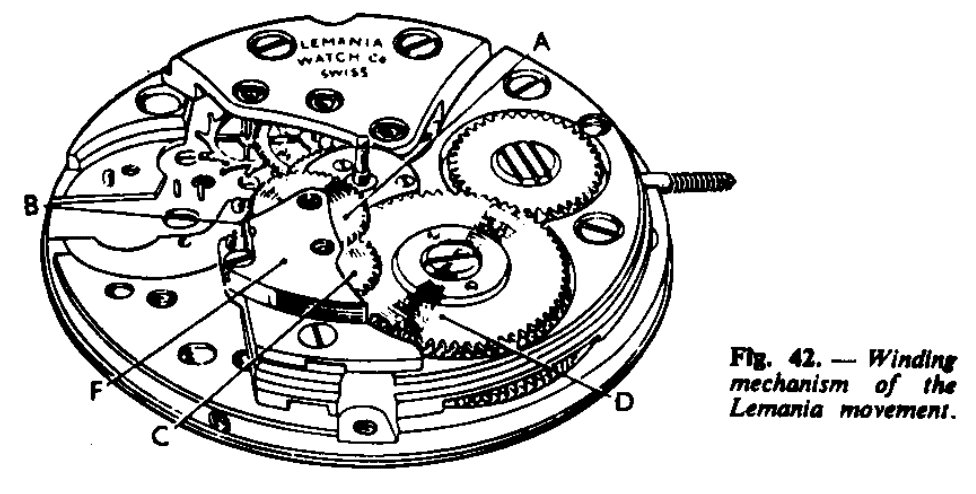
As the top ratchet wheel rotates through the operation of the rotor, the notches in the under-side of the ratchet contact the three-pronged spring and cause the mainspring to wind and the wire click B to act as a ratchet click, until the click of the main ratchet wheel takes over.
When the watch is wound by hand the lower ratchet is made to rotate in the conventional manner and the notches in that wheel contact the three-pronged spring and so the mainspring is wound without interfering with the automatic mechanism. To dismantle the automatic work, remove the screw A (Fig. 41), and withdraw the steel plate B. The rotor can then be lifted up off the centre post and away from the movement. Next, let the mainspring down by holding back the wire click B (Fig. 42). The main click of the mainspring ratchet wheel then holds the mainspring up and this can be let down in the usual manner. Remove the bridge F, and then the two wheels, Remove the ratchet wheel screw and lift off the top ratchet wheel, the three-pronged spring and then the lower ratchet wheel.
When re-assembling particular attention must be given to the freedom of the two ratchet wheels, and satisfy yourself that the three-pronged spring is operating correctly in the rectangular sinks or notches without excessive tension. For correct oiling refer to oil chart (Fig. 43). This movement is of sturdy construction and the design is most simple and highly efficient.
LONGINES
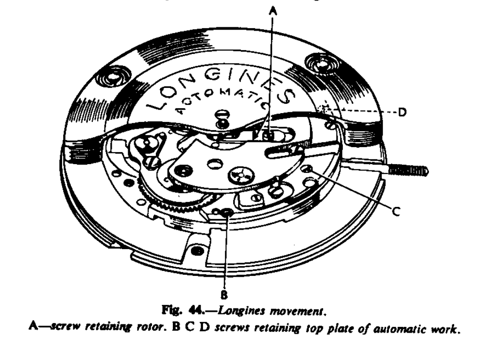
Made by the Longines Watch Co., St. Icier, Switzerland, and known as calibre 22A, the rotor of the Longines automatic revolves through 360° and winds both ways.
First remove the movement from its case by releasing the winding button and shaft, then loosen the two screws holding the movement in its case. Unscrew the screw A (Fig. 44), and withdraw the fork piece. Hold back slightly the rocking arm C (Fig. 45) and lift the rotor straight up and off its post. The automatic work operates as follows: fixed arm by a shouldered screw, which is held towards the heart piece by a spring so that as the rotor revolves in either direction the rocking arm, pivoted at A (Fig. 45) is made to swing in and out.
The underside of the rocking arm (Fig. 45) has fitted to it the steel wheel and pinion B; gearing into the larger wheel is the small steel wheel which is located in an oval hole; the wheel is shoulder-screwed on to a disc and this carriage is kept in contact with the steel plate D by a spring. The steel plate D has a milled edge D1, and as the small wheel rotates in an anti-clockwise direction it passes the milled edge (disengaging), but when reversed the teeth of the milled edge loc it, so that this wheel and consequently the larger wheel can rotate in one direction only; the milled edge and the smaller wheel act as a fine click.
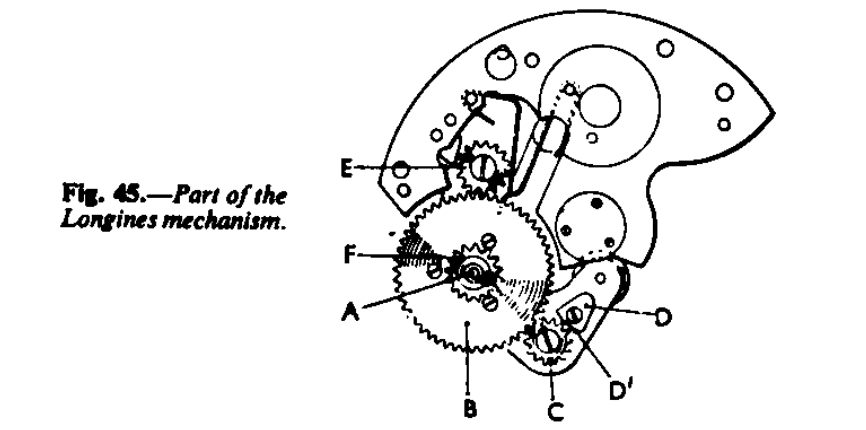
The large wheel also gears into the steel wheel E, which is located in an oval hole and is controlled by a steel plate with a milled edge, similar to the plate D, As the large wheel rotates in a clockwise direction both the small wheels rotate anti-clockwise and are free to pass the milled edge, but are locked when reversed; we shall see the object of this presently. The pinion F gears direct into the main ratchet wheel. As the rotor rotates backwards or forwards the wheel B is made always to advance by virtue of the locked wheel C. The wheel E acts as a fine click, so that advantage is. Taken of the slightest movement of the rotor and this wheel holds up the mainspring until the ratchet click takes over.
To resume taking the automatic work to pieces : having removed the rotor spring A (Fig. 44), remove the three screws B, C, D, and take off the top plate of the automatic work. Now remove the rocking arm and unscrew the steel roller and the two wheels. Unscrew the wheel from the underside of the plate. It is not necessary to remove the two steel plates with the milled edges, and it is not necessary to dismantle the rotor. It will be noted that the weight of the rotor is held to the segment by studs and springs. The object of this is that these springs take any violent shock and so prevent damage to the centre pivoting. The springs are so designed that they act as shock-absorbers both in the horizontal and vertical directions. Having cleaned the movement and the automatic work, re-assemble the automatic last after movement has been fitted into its case.
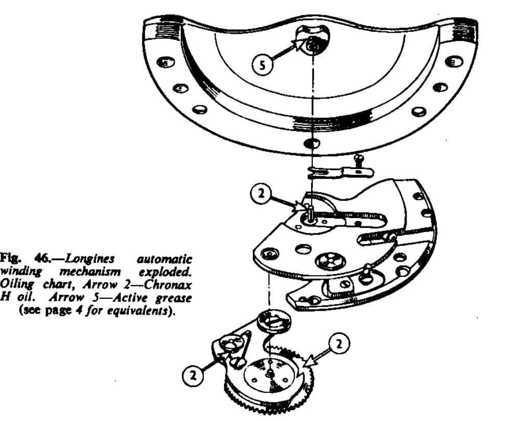
Messrs. Longines give special instructions about oiling. They recommend Chronic H for the light oiling and HHH for the heavy.
Grease the interior of the mainspring barrel with graphite before winding in the mainspring. This enables the slipping hook to slide round without jerking. Before assembling the barrel into the movement check the mainspring action. Refer to the oiling chart for the correct method of oiling.
It is essential that all moving parts of the automatic work should be perfectly free. This movement is well deigned and beautifully finished.
MOVADO
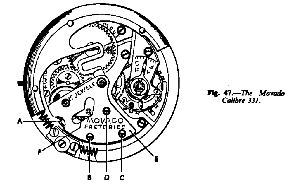
The Movado Factories, La Chaux-de-Fonds, Switzerland, make two automatic models, both of the same size, but working on different principles. Each is fitted with a rotor making a part revolution and banking upon buffer springs and they each wind in one direction only.
One model is calibre 331, which Movado claim to be the flattest automatic yet made, and the other calibre 221, also known as the Tempomatic.
Dealing with calibre 331 first, in Fig. 47, the rotor consists of a steel plate cut to form a spring. If the watch receives a shock either horizontally or vertically, the spring part of the rotor arm give so that the centre pivots of the rotor working in jewelled holes are relieved of shock. Riveted to the outer edge of the rotor is a band of heavy metal. Fixed to the arbor of the rotor is a steel pinion which engages with the teeth cut into the end of a brass rocking arm. Mounted on to the rocking arm is a steel fine-toothed ratchet wheel with pinion attached and this pinion gears into the transmission wheel of the keyless mechanism.
Fitted on to the rocking arm is a click and spring and a similar click and spring is fitted to the top plate of the movement. As the rotor oscillates, the click on the rocking arm gathers up the teeth of the fine-toothed ratchet wheel and the click fitted to the top plate retains the wheel in position until the click of the main ratchet wheel takes over. The action is quite simple and well designed.
To dismantle, first turn the winding shaft a little and draw back the retaining click A, fig. 47, so that the automatic work is free of the power of the mainspring. Then remove the three screws B, C, D, and lift off the bridge E. The rotor can now be removed, also the rocking arm and the retaining click. Remove the three screws holding the fine-toothed ratchet in position and also the gathering click F.
Re-assemebly
After cleaning in the conventional manner of the whole movement, including the automatic work, and facing re-assembled the movement, proceed to assemble the automatic mechanism. Movado recommend lubricating the mainspring and the slipping bridle with graphite grease-a mixture containing 1 to 2 per cent. Graphite. Oil the seating of the fine-toothed ratchet wheel with clock oil and replace the three screws. Fit the gathering click and also the retaining click into position and apply a little clock oil to their bearings. Oil the lower pivot holes of the rocking arm and the rotor with clock oil. Place the rotor in position and then the rocking arm. Arrange so that when the rotor is midway between the buffer springs the pinion leaves engage in the teeth in the centre of the rack of the rocking arm. This is important, to ensure that the leaves of the pinion in the rotor engage the rocking arm teeth during a complete swing of the rotor.
Oil the upper pivots of the rocking arm and the rotor with clock oil. Apply clock oil sparingly to the teeth of the fine-toothed ratchet wheel and work the rotor to and fro so that the oil is picked up by the noses of the gathering and retaining clicks.
The other movement is calibre 221, also known as Movado Tempomatic, fig. 48. The rotor is of similar design to calibre 331, but without the spring device. Fitted to the rotor is a gathering click and spring, A, fig. 48. Pivoted under the plate B are four steel wheels with a retaining click engaging into the second wheel.
The fourth and last wheel has fixed to it a pinion which gears into the wheel fitted to the barrel arbor above the main ratchet wheel. The main ratchet wheel is squared on to the barrel arbor in the normal manner, and on the top of the wheel is a small steel wheel with ratchet shaped teeth. The top wheel C, fig. 48, has fitted to its underside a click and spring. It has a round hole and fits on to the top pivot of the barrel arbor. This wheel is held in position by a washer and screw.
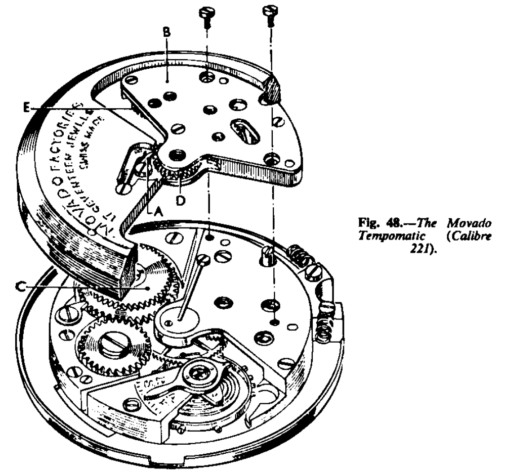
The action is as follows: As the rotor oscillates backwards and forwards the click A, fig. 48, gathers up the wheel D which transmits to the next wheel; this last-mentioned wheel is controlled by a retaining click and spring holding up the automatic train until the click of the main ratchet wheel takes over. The pinion of the last wheel causes the wheel C to rotate and through its click the ratchet wheel is made to rotate and so the mainspring is wound.
If the watch is wound manually, the main ratchet wheel is made to rotate and the click fitted to the wheel C idles over the teeth of is ratchet wheel, and the train of the automatic work is not interfered with at all. It is a simple, clever, and well-designed movement. The oiling instructions recommended by Movado are similar to those given for calibre 331. The click between the two ratchet wheels is oiled with clock oil and also the surface of the upper wheel where it contacts the small ratchet wheel. Apply a little clock oil to the undersurface of the washer.
OMEGA
Made by Omega Watch Co., Bienne, Switzerland, the Omega automatic has a basic reference number of 243, fig. 49. Other numbers bay be fund in some models and these additional numbers refer to alternations or modifications (height of hands, etc.), where they differ from standard.
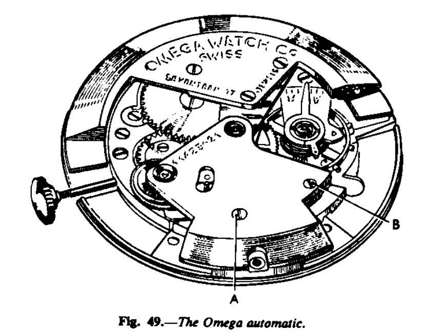
The rotor oscillates through a segment of a circle and bumper springs are employed. The winding operations as the rotor moves in one direction only. The automatic winding functions in the following manner: Fixed to the rotor is a steel plate with pivoted arbor. On the end of this plate are cut seven teeth which engage with the teeth cut on the end of the rocking arm. Fitted to the rocking arm and free to rotate is a ratchet wheel and with this two clicks engage, one fitted to the rocking arm and the other to the top plate of the watch movement. Fixed to the ratchet wheel is a pinion which gears into the transmission wheel of the keyless work. As the rotor swings backwards and forwards, the arm rocks from side to side and the click attached to it gathers up the teeth of the ratchet to move it forward. The click fitted to the top plate of the movement holds the ratchet wheel in position until the main ratchet wheel of the mainspring takes over. The design is very simple and sturdy and the execution of a high order.
To dismantle, first release the click fitted to the rocking arm by inserting a fine point it the hole of the auto-wind bridge, where the pin fixed to the click can be seen. If the click is moved far enough back its spring will hold it there, free of the fine-toothed ratchet wheel. While in this state let the mainspring down in the conventional manner, as explained in “Practical Watch Repairing.” The two screws, A and B, fig. 49 can now be removed. Lift off the bridge of the automatic work and then the rotor and the rocking arm. Remove the click from the rocking arm, and unscrew the fine-toothed ratchet wheel. Remove the click from the top plate. The automatic winding parts are cleaned in the conventional manner, and before describing re-assembly here are a few observations about the mainspring by the Omega Watch Co.
The slipping device is as shown in Fig. 49. If it is found necessary to remove the mainspring because of thick oil, etc., clean both the spring and attachment by drawing them through a piece of rag, holding the spring between the ponds of tweezers, without causing deformation. The spring should not be washed it any liquid. The slipping attachment is cleaned in a similar manner. Before replacing the slipping attachment and mainspring pass them in the fold of an oily rag, holding the spring as before, so as to apply a thin film of oil to both sides of the spring and the attachment. Use the special winder to insert the attachment and spring. When the arbor and cover have been assembled check that the spring can be wound at least five turns before slipping occurs.
Before barrels are passed in the factory they must give 5½ turns before slipping. One should barely be able to feel the slipping occur if the action of the attachment is correct. If the desired result is not obtained, remove the mainspring and attachment. Check the outer surface of the attachment for smoothness. If necessary, open out the slipping attachment so that it will grip the inside of the barre harder. If there is any doubt about the attachment do not hesitate to change it and if slipping persists, thicker attachments are available.
Now to re-assemble the automatic work: When all the parts have been inspected and found to be in good condition and perfectly clean they are lubricated. The points listed below should be oiled with a relatively thick oil (Moebius No. 1 chronometer oil or Moebius 9010). Use an exceedingly small quantity, just sufficient to form a very thin film.
The bearings of the two clicks, one on the rocking arm and the other on the top plate. The ends that operate on the ratchet teeth and also where the springs bear on to the clicks. The teeth of the transmission wheel. The fine teeth of the ratchet wheel. The teeth on the rocking arm and also the teeth on the rotor. The bearing surfaces of the fine tooth ratchet wheel in the rocking arm. The pivots of the rocking arm and the rotor are oiled in the conventional manner. Watchmakers may hesitate to oil the teeth of wheels, but this procedure is recommended by the Omega Watch Co. And such advice could with advantage be applied to other makes of watches with a similar system of automatic mechanism.
The buffer springs should be wiped over with an oily rag to ensure that their entire outer surface is sufficiently lubricated so as to minimise the effects of rubbing.
See that the two clicks are perfectly free and that they do not have excessive end-shake, to ensure that they engage with the fine-tooth ratchet correctly. See that the click springs engage in the grooves formed in the clicks.
Oil the lower pivot hole of the rocking arm, place it in position, then oil the lower pivot hole of the rotor. Arrange so that the last tooth of the rotor segment engages in the last space of the rocking arm segment, Fig. 51. This is essential as it ensures that the rotor will traverse its full arc in both directions.
Replace the automatic bridge and oil top pivots of rotor and rocking arm.
Fig. 52 shows the oiling chart. Check that during the complete travel of the rotor three teeth of the fine-tooth ratchet are gathered up by the click on the top plate.
PATEK PHILIPPE
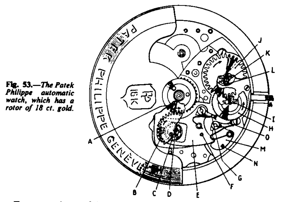
The automatic watch made by Patek Philippe of Geneva, Switzerland, is known as calibre 12’’ 500. The quality of the movement is superb, the steelwork is straight-grained with edges broken and polished. The rotor revolves is full 360° and winds in both directions. In order that the rotor shall be of the correct weight a solid piece of 18 ct. gold is used. The action is very simple and most ingenious and there appears to be nothing to go wrong, its action is as follows (Fig. 53).
For convenience of description the rotor is travelling anti-clockwise. Fixed to the rotor is the wheel A which gears with the wheel B. This wheel is pivoted at C. Secured to the wheel B is the ball-race D and it will be noted that it is screwed on out of centre so that as the wheel B rotates the race is eccentric. The cam E, pivoted at F, has a fork-like part which embraces the ball-race. The click G, with its spring, is pivoted on to the cam and engages with the ratchet wheel H. Fixed to the ratchet is the pinion I which gears with the wheel J, and fixed to this wheel is the pinion K which in turn gears with the transmission wheel L, and so to the main ratchet wheel squared on to the barrel arbor.
As the wheel A rotates in the direction of the arrow the wheel B will cause the ball-race to move the lever E upwards. This action will cause the click G to move the ratchet wheel H in the direction of the arrow and so eventually to wind the mainspring. When the rotor travels in a clockwise direction the cam E will be moved down and the click G will pass freely over the teeth of the ratchet wheel, but the end of the cam E engages the cam M, pivoted at N, and the click O with its spring, is pivoted on this cam. The movement causes the cam M to move up and thus the ratchet wheel H is impelled forward, again in the direction of the arrow.
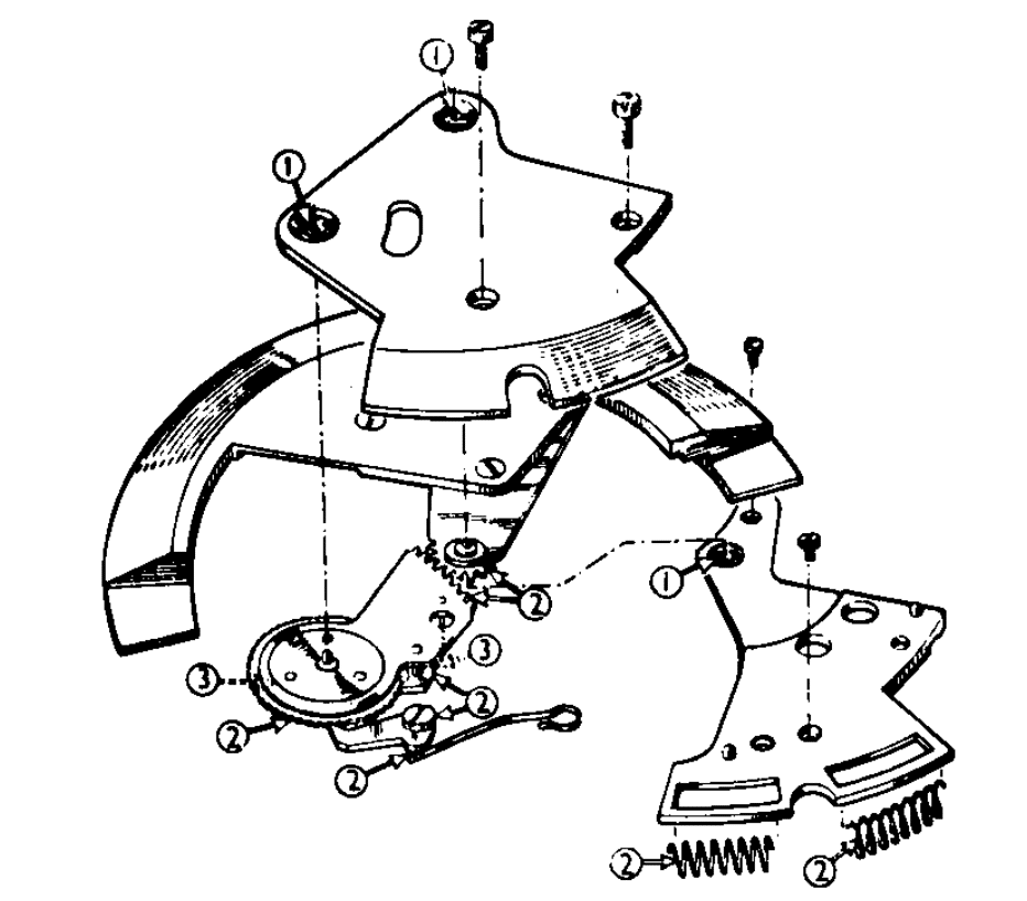
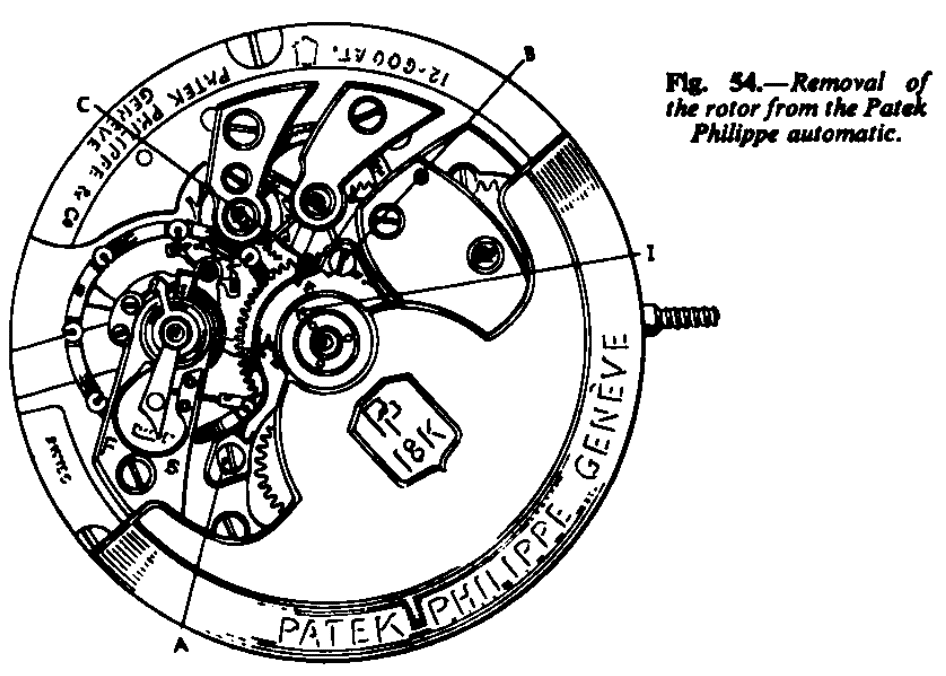
Patek Philippe recommend the following procedure when dismantling the movement.
1. Move the rotor to one side as Fig. 54 and the remove the two screws A and B. Withdraw the steel locking piece C and this will release the rotor which can now be lifted up and away from the movement.
2. Remove the case ring.
3. Remove the bridge A fig. 55, and the two wheels B and C.
4. Release the tension of the mainspring by disengaging the click D Fig. 55.
5. Remove the bridge E fig. 55 and the parts F, G and H.
6. The movement is then dismantled in the conventional manner.
Special note.- To release the mainspring it is preferable to remove the wheel C fig. 55 first. This will then engage the click D Fig. 55 and the mainspring is allowed to be let down by controlling the winding button.
Re-assembling. Before assembling the automatic mechanism make sure the crown wheel, ratchet wheel and the transmission are perfectly free. The face of the ratchet wheel must be oiled.
The automatic work is then assembled in the same manner as it was taken to pieces, but in the reverse sequence, starting with the wheel H Fig. 55.
The Rotor. Special attention.-Make sure that the mark I on the rotor and the mark J on the wheel with the eccentric disc face each other, so as to ensure the maximum winding potential. Also see that the rotor is perfectly free.
Oiling.-Apply watch oil to all winding wheel pivots of the automatic winding mechanism: rotor arbor K; click pivots L and M and very little on the teeth of the winding wheel C. Apply clock oil to the eccentric disc F; to the fork lever and to the point of the same lever where it engages the lever G.
PIERCE
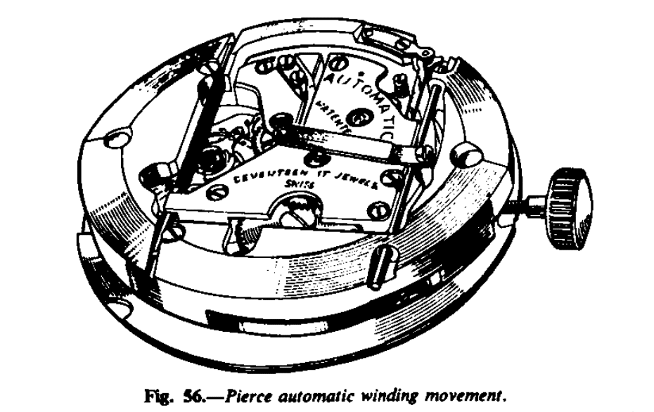
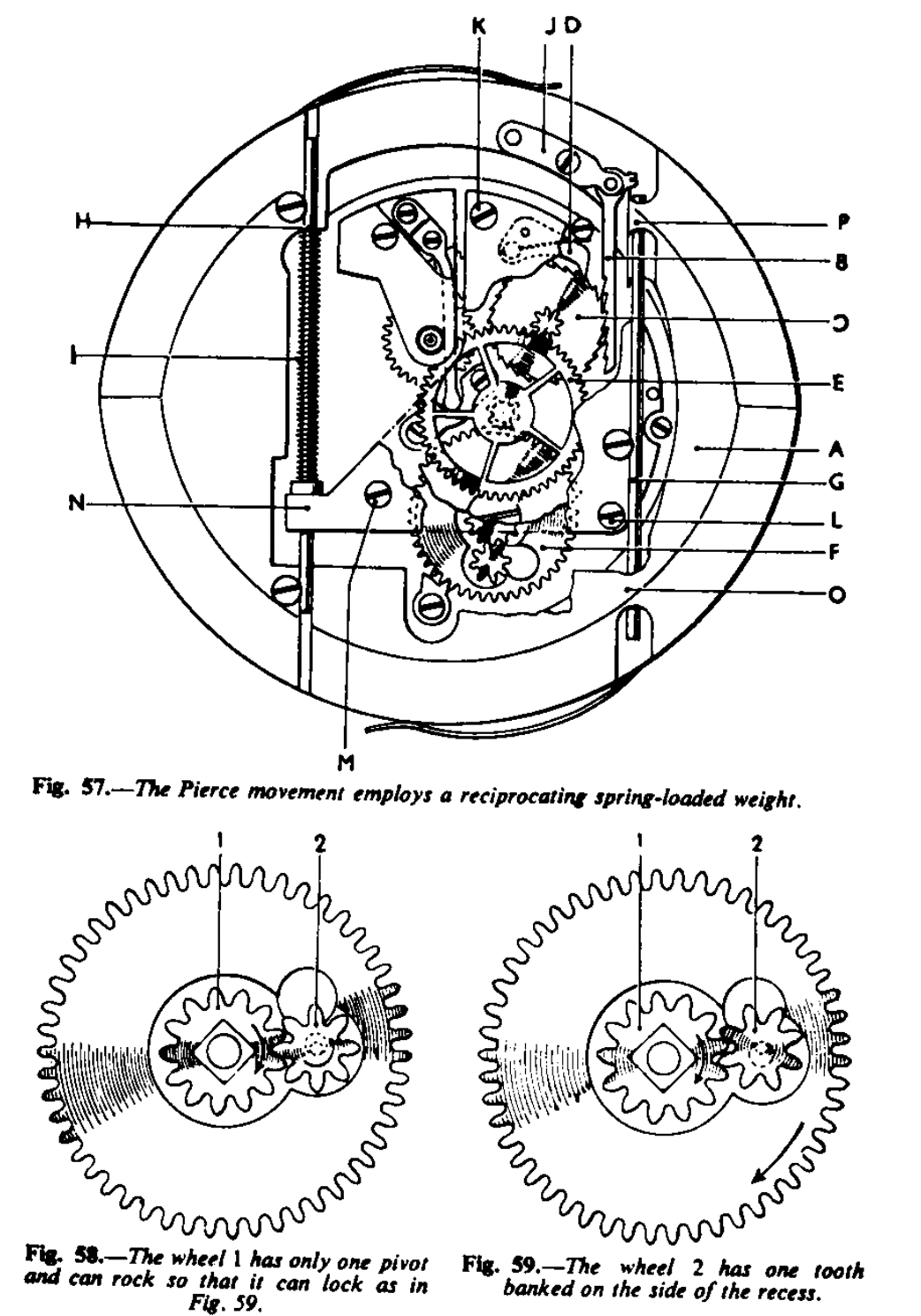
The movement by Pierce S.A., Bienne, Switzerland, is 8 ¾’’, cal, 861 AUT., and is an exception inasmuch as it has no rotor. It is wound by a reciprocating weight which surrounds the movement. Fig. 56 is a general view of the movement. The action of automatic mechanism is as follows: attached to the weight A (Fig. 57) is a rack with ratchet teeth B. This engages into a wheel with fine ratchet teeth C, and fixed to it is a pinion.
When this wheel is moved forward by the rack it is kept in position by the click and spring D. The pinion of this ratchet wheel engages into the wheel and pinion E. The pinion of the wheel E gears into the upper ratchet wheel F, which is squared on to the barrel arbor. The under ratchet wheel has a round hole and fits freely on the barrel arbor. This ratchet wheel is recessed to accommodate the two steel wheels as shown in Fig. 58. These two small wheels really constitute a form of ratchet work which is most ingenious. It operates as follows: – When the autowinding is in action the lower ratchet remains stationary. The wheel 1 (Fig. 58) is squared on to the barrel arbor.
The wheel 2 is fitted with one pivot only, which is located in the relatively large hole in the ratchet wheel. This enables the wheel to rock backward and forward; therefore as the top ratchet wheel is made to rotate, the wheel 1 also rotates and with it the wheel 2; but if the power of the autowinding were taken of and the wheel 1 to reverse, a tooth of the wheel 2 will bank on the side of the recess as shown in Fig. 59. It will be seen, therefore, that if the lower ratchet wheel is made to rotate, as during manual winding, the wheel 2 (Fig. 59), butting on the recess, will cause the wheel 1 to rotate and so wind the mainspring; in these circumstances, the click engaging the wheel moves and so holds up the mainspring. When autowinding, however, this click does not actually move but still holds up the mainspring.
The weight reciprocates at right-angles to the pendant, I.e. from 6 to 12.
It is held in position and travels on the guide rods G and H (Fig. 57). The spiral spring, F, embracing the guide rod H, facilitates the return of the weight, ready to be jerked in the forward direction to wind.
To dismantle: first place the spring of the rack click D (Fig. 57) to the other side of the banking screw; this will free the rack of the wheel it engages with. Remove the rack B by unscrewing the bridge, J, then withdraw the rack. Next let the power of the mainspring down in the conventional manner; unscrew the three screws K, L, M, and the weight complete with the bridge, which forms the top plate of the automatic mechanism, can be lifted off and away from the movement.
The wheel with ratchet teeth and the next wheel can now be removed. Unscrew the ratchet wheel screw and remove both the upper and lower wheels, together with the two small wheels.
To re-assemble: after cleaning the movement and having fully assembled up to the automatic work, it is convenient to place the movement in its case to assemble the automatic mechanism. Oil with clock oil the pivot upon which the lower ratchet wheel fits, place the wheel on the barrel arbor square, then oil that part upon which the small wheel rests and place it in position. Now screw the top ratchet into position. Oil with watch oil the lower holes of the two autowind wheels and also the click, and place these parts into position.
Screw on the top plate with the weight. Insert the rack-apply a little watch oil to the teeth of the rack and grease with clock oil the guide rods where they contact the weight, I.e. at points N, O, P (Fig. 57).
To check after assembling: hold the watch vertically with the pendant on the left. Lift the weight up with a pointed peg and observe that the rack should gather up five teeth; release the weight and it should drop to the bottom. Reverse the watch so that the pendant is at the right and, during the early stages of winding, the weight being lifted should wind as it falls. Eventually as the mainspring becomes wound the falling weight will not wind by virtue of its own weight alone, but will require a jerk. Oil with watch oil the pivot holes in the top plate. Finally, when winding manually, wind slowly, otherwise the rack teeth may be damaged.
REVUE
The Revue watch is made by Thommen Watch Co., Ltd., Waldenburg, Switzerland. The movement is 13½, with 8¾’’ actual watch movement. Fig. 60 shows a general view; the rotor operates through a segment of a circle with bumper springs, the mainspring being wound as the rotor rotates in either direction.
The action of the automatic winding mechanism is as follows: fixed to the rotor is a steel pinion which gears into two sector rack gears. Fixed to each of the racks is a click and spring which operates upon a very fine ratchet toothed wheel; this ratchet wheel has a gathers up the wheel and the other click is just made to free-wheel back; reverse the direction of the rotor and the first-mentioned click will pass the teeth and the other click gathers up the wheel always in the same forward direction. The pinion of the fine-toothed ratchet wheel gears into the transmission wheel of the keyless work. This system is simple and sound design.
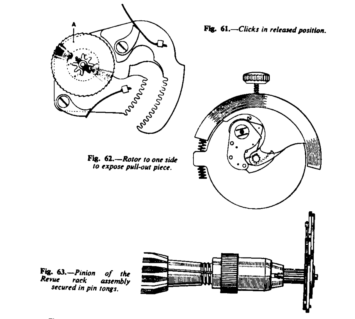
To dismantle: the autowinding mechanism is removed before taking the movement from its case. Unscrew the top plate of the automatic work, A, B (Fig. 60), then cause the ratchet wheel A (Fig. 61) to move slightly by turning the winding button a little so as to release the tension of the mainspring on this wheel. Lift off the rotor and the sector rack assembly complete. The movement can now be removed from its case in the normal manner. If it is desired to remove the movement complete with the autowinding, move the rotor to one side, as in Fig. 62, to expose the pull-out piece screw. It is of vital importance that the automatic winding ratchet wheel shall not be injured, as the teeth are very fine and the wheel being made of brass is soft and easily damaged.
The rack assembly works without any oil or grease; it operates efficiently when left quite dry. It is therefore not necessary to take it to pieces for purposes of cleaning, but should it be necessary to fit a new part to this assembly, proceed as follows to dismantle: –
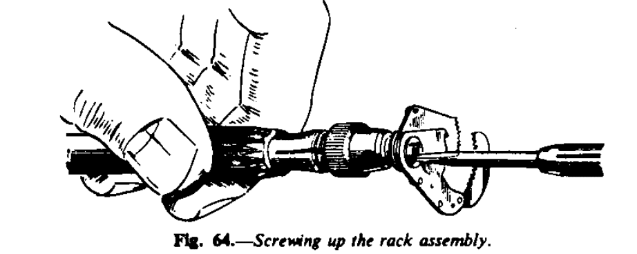
First, arrange the two clicks as Fig. 61, then secure the arbor of the pinion in the pin tongs as Fig. 63 and with a screwdriver unscrew the screw as shown in Fig. 64.
After cleaning, assemble the movement in the normal manner. It is convenient to fit the movement into its case before assembling the automatic mechanism.
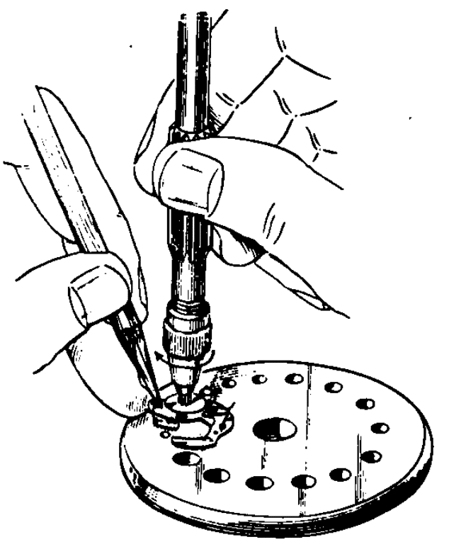
Having cleaned the parts of the automatic work, proceed to assemble as follows: if the sector rack has been dismantled, place the nut on a steel plate with a hole to receive the pivot of the ratchet wheel pinion. Arrange the clicks on the sectors as Fig. 61, place the larger sector in position on the nut, click upwards. Apply a little pressure with a piece of peg-wood to bind the steel nut. Now screw the ratchet wheel, held in the pin tongs, and screw up tightly (Fig. 65). The ratchet wheel should in the circumstances be held, since it would tend to loosen the pinion in the wheel and it is essential that this pinion should be fixed tightly. Release the clicks and see that they engage with the ratchet wheel correctly. Finally, ensure that the nut us tight.
To reiterate: it is important not to apply any oil or grease to this assembly.
To continue with the general assembly of the automatic work: fit into position the sector assembly, first applying watch oil to the lower hole. Arrange the sectors so that the small hole in the base plate is in line with the rivet end of the click spring of the small sector. Apply clock oil to the lower hole of the rotor, then place the rotor in position so that it is midway between the bumper spring, as shown in Fig. 69. This will ensure the full and equal operation of the sector rack gears with the pinion of the rotor. Ot only remains to oil the two top pivots, the ratchet wheel and the rotor, and the work is complete.
ROLEX
There are two models of the Rolex automatic winding watch, made by the Rolex Watch Co. Of Geneva, Switzerland: the Tudor Prince cal. 390 and the Rolex Perpetual cal. 1000. As the fundamental principle of the automatic mechanism is similar in both watches, the cal. 1000 will be described since this is the best known Rolex model in the past.
Where the cal. 1000 differs from the Tudor in part is that the cal. 1000 is more highly finished. It is fitted with 21 jewels and an improved shock-absorbing system to the balance staff; the top escape wheel jewel hole, and end-stone are detachable. This system facilitates the adjustment of the endshake of the escape wheel and is convenient for the removal of these jewels should partial cleaning necessary.

The Tudor has 17 jewels.
In with calibres the rotor revolves the full 360 degrees, winding in both directions.
The action is as follows: the rotor arbor A (Fig. 67), which is riveted to the rotor, has two flats cut on its lower end. These fit into a similarly shaped hole in a small steel wheel B which gears into one of two brass (nickelled) wheels. These two wheels-the reverse wheels-C (Fig. 68) are exactly similar. These two wheels-the reverser wheels-C (Fig. 68) are exactly similar. They are each fitted with a fixed ratchet wheel D (Fig. 69) and two long loose clicks E. The two clicks are held in position by a ring F which is snapped on in similar fashion to a barrel cover. Over this ratchet wheel and clicks is fitted a pinion G fixed to a type of lock-washer plate H.
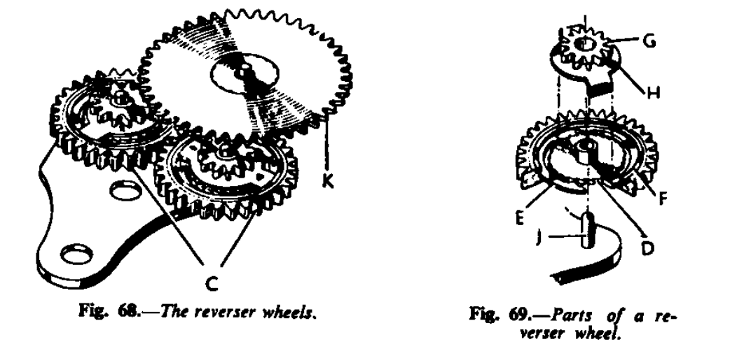
The wheels and the pinions are free to rotate on studs J which are riveted to the plate carrying the wheels. Both the pinions gear into a brass wheel with pinion K (Fig. 70) which also fits on a stud riveted to the plate. Therefore, if one of the reverser wheels C is made to rotate in either direction, the wheel K will rotate in one direction by virtue of the heads of the clicks pressing upon the rectangular plates to which the pinions are fixed; one pair of clicks will idle over its ratchet wheel while the other pair is being pulled round the heads pushing the pinion through the rectangular plate. When the direction of rotation is reversed the second pair of clicks comes into action.
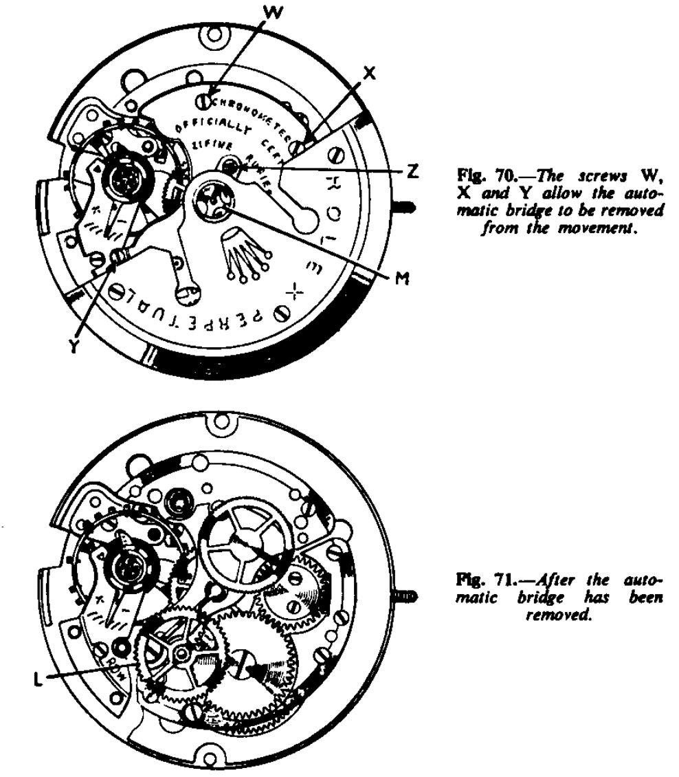
The pinion of K gears into another brass wheel with pinion L (Fig. 71) and it is the pinion of this last wheel which gears direct into the ratchet wheel of the barrel.
Although the system may sound complicated to describe it is, in fact, simple and, what is more important, quite obvious and straight-forward, presenting no difficulty to the skilled watch repairer.
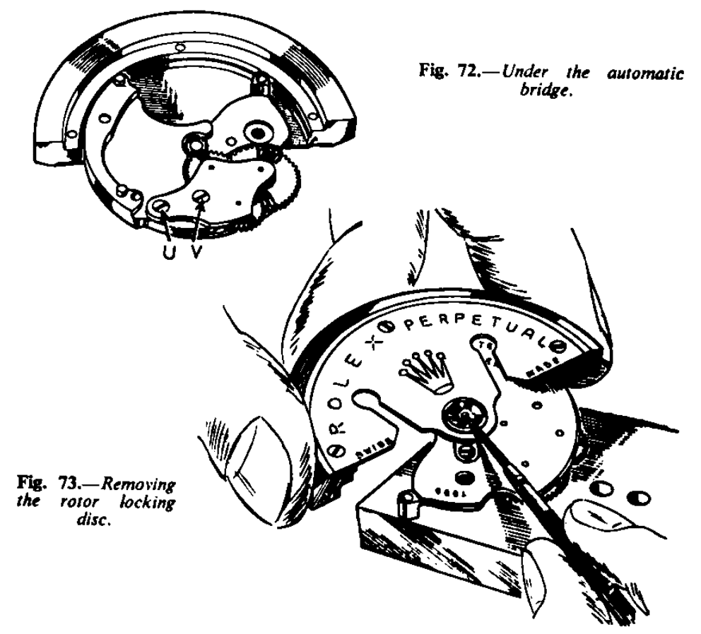
To dismantle, first let down the mainspring in the conventional manner, then remove the movement from its case. Unscrew the three screws W, X, Y (Fig. 70) and lift up and away from the movement the automatic bridge complete with the rotor. The movement will then be left with the wheel L (Fig. 71) gearing into the barrel ratchet wheel. Remove this wheel. Now place the automatic unit on a stake as in Fig 71 and remove the rotor locking disc M (Fig. 70) with the blade of a screwdriver, pressing against the edge with the slot, as shown.
This will release the rotor post and with it the small steel wheel B (Fig. 67) with the rounded end and a rectangular hole. Lift the rotor up and away from the unit.
Next place the automatic bridge upside-down on the bench and remove the two screws U and V (Fig. 72) and prise up the plate. The three wheels under this plate are almost sure to come away with the plate. Then remove the brass wheel K and the two reverser wheels C from their studs (Fig. 68). The pinions are lifted out of the wheels and the clicks E (Fig. 71) are removed by prising up the steel snap-on ring F (Fig. 69). To do this without injury use a piece of brass wire filed up like a screwdriver blade.
Should it be required to fit a new mainspring only it is not necessary to take the automatic mechanism of pieces. Remove screw Z (Fig. 70) and then turn the rotor to expose the other screw. Unscrew this screw half a turn and spring the steel plate round to one side. This will release the large jewel hole and it will be possible to remove the whole of the automatic mechanism as one unit.
Re-Assembly
Having cleaned the movement and all the automatic components in the usual manner and reassembled the movement, the automatic work may be assembled.
Place the plate with studs upside-down on the bench (Fig. 68). Apply a little watch oil to each of the three studs then place the two reverser wheels C in position. Fit in the clicks E and snap the ring F into position. See that the clicks are equidistant so that when the pinions G (Fig. 69) are placed in position the projections of the lock washer type plates H to which the pinions are fixed fit between the head of one click and the tail of the other.
Apply a fair amount of watch oil to the teeth of the ratchet wheels D. Place the brass wheel K in position. With the automatic bridge flat on the bench place the plate with its three wheels in position and screw down, the wheels will not drop off as the oil holds them in position.
Move one of the steel wheels C backward and forward to ensure they are free and that the reverser action is correct. The brass wheel K should move in one direction only.
Now place the rotor upside-down on the bench and oil the rotor post with clock oil. Next place the automatic bridge on to the rotor, also upside-down. Fit the small steel wheel B into the end of the rotor arbor, recessed side uppermost, and place the rotor fixing post into the centre of the rotor arbor.
Hold the assembly in the left hand-in tissue paper-with the forefinger of the left hand pressing against the end of rotor fixing post, and in this position turn the assembly over and replace the locking disc. It will be found that with slight pressure, using the blade of a screwdriver, it snaps into position once the slotted side has been presented to the groove in the end of the fixing post.
Apply clock oil to the lower hole of the wheel L which gears into the barrel ratchet wheel and place that wheel in position. Now fit the automatic unit on to the movement. See that pinion of the brass wheel K between the plates engages into the brass wheel L (Fig. 71). Manipulate the top pivot of wheel L into its hole and screw the bridge down. Apply a little clock oil to the top pivot of wheel L and the assembly is complete. See oiling chart (Fig. 67).
Two improvements in connection with the case are worth mentioning. Rolex have reverted to the screw-down type of button we are familiar with in their Oyster watches. It is now vastly improved inasmuch as that even if the button is not screwed down at all it is still waterproof; thus it is a double waterproof system.
The glass fits on to an outside rim of the case. It is then made doubly secure by a ring pressed over the glass and gripping the side of the glass. The advantages of this system are that it provides a double lock and a new glass can be fitted without removing the movement from its case or even opening it. The ring is removed with the blade of a knife as one would open an ordinary bezel.
The general construction and finish of this movement is of a high order and the reverser system is most ingenious and certainly unique.
ROTOMATIC (Ebauches, S.A.)
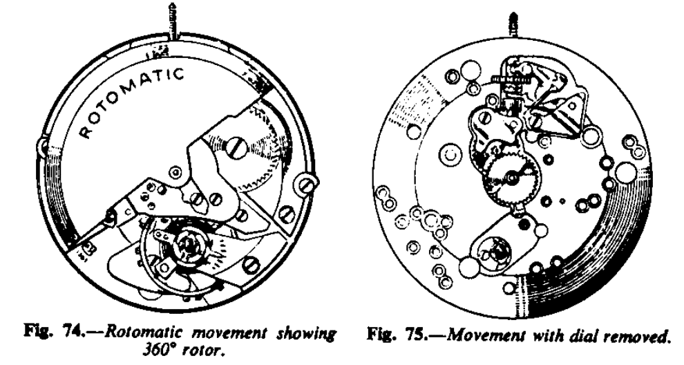
Made by A. Schild S.A., Grenchen, Switzerland, the Rotomatic has an 11½’’ movement = 26 mm calibre 1361. The toro rotates through 360 degrees and winds in both directions, and there is a centre seconds hand. The movement is shown in Fig. 19 and, with the dial removed in Fig. 20.
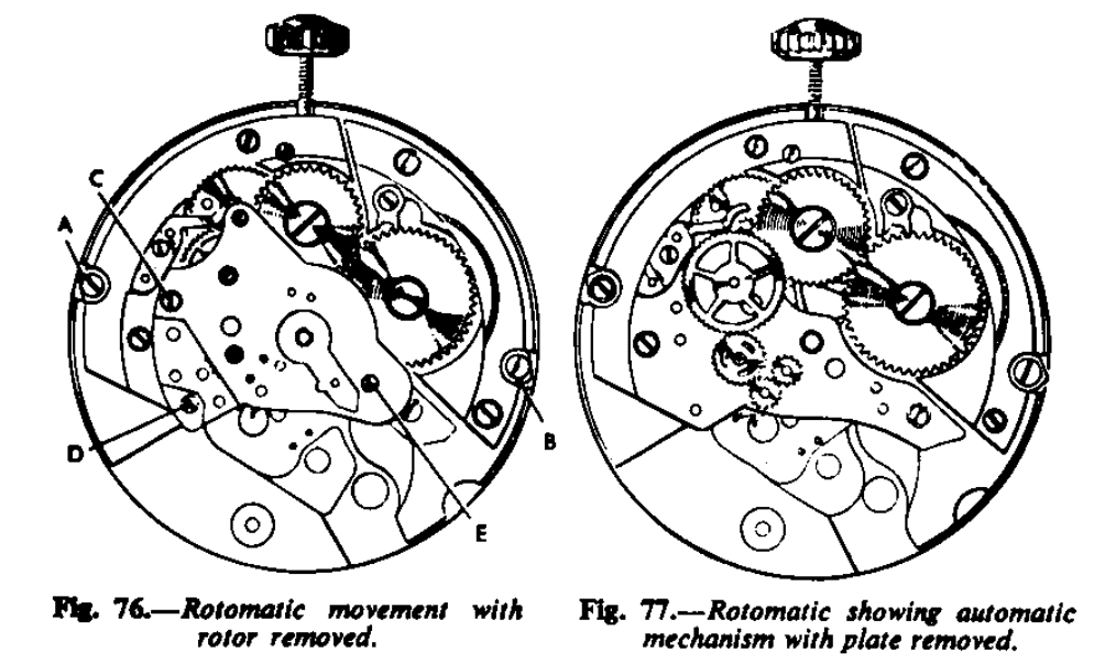
To remove the movement from its case, turn the dog screw A and B (Fig. 76). Remove the winding shaft and the movement can be lifted from the case. To take the automatic mechanism to pieces remove the click bridge A (Fig. 78) and the click. Refit the winding shaft and then let the mainspring down by holding back the ratchet click, controlling it by the winding button. Then remove the three screws C, D, and E (Fig. 76). The top plate of the automatic worn can now be lifted off and with it the rotor.
The action is as follows: a brass wheel B (Fig. 77) fixed to the rotor gears into first one steel wheel and then the other, C, which are both pivoted upon a small steel rocking arm D. The arm rocks to and fro and as the rotor wheel engages forward with one wheel then rotating in one direction, and then as the rotor rotates in the reverse direction it disengages and engages forward with the other wheel, with the result that the wheel and rocking bar wheels engage into E alternately, causing it to rotate in one direction only.
A click engages the last-mentioned wheel and this wheel engages another wheel with pinion attached, F. This pinion in turn engages a steel wheel G with a loose pinion H, the lower end of which is cut with ratchet teeth engaging another ratchet fixed to the wheel similar in action to the crown and castle wheels of keyless work. The result is that the pinion can rotate in one direction only. This ratchet pinion gears into the transmission wheel I and so to the main ratchet of the movement and thus the mainspring is wound.
As the rotor moves in either direction the wheel next to the rocking arm is held up by the click until the click of the ratchet wheel takes over, thus the greatest advantage is taken of every movement of the rotor.
When winding up the mainspring by the winding button, the ratchet pinion of the last wheel of the automatic train just reverses, so that the wheels of the automatic work are not made to rotate. The ratchet pinion is kept in contact with the ratchet in the wheel by a spring J (Fig. 78). Fig. 77 shows the train of the automatic work. The movement is so designed that the barrel can be removed, to fit a new mainspring without even taking the movement from its case. To continue taking to pieces the rotor is removed by unscrewing the steel plate K (Fig. 78) on the top plate of the automatic work. The up-and-down movement of the rotor is controlled by the spring K (Fig. 78). To give less freedom it should be bent down. For method of oiling refer to Fig. 78.
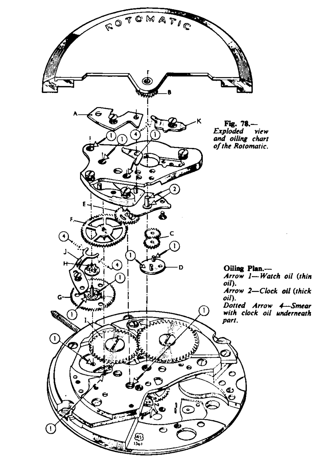
TISSOT
Made by Chs. Tissot et Fils S.A., Le Locle, Switzerland, there are three Tissot models with centre seconds hands and three with off-set seconds hands, diameters being 28.00mm., 28.50 mm. And 31.00 mm. The automatic mechanism is the same in each mode. Calibres are 28-1, 28.5-1, 31-1 off-set seconds and 28-21, 2805-21, 31-21 centre seconds. See Fig. 79 for general view of the movement.
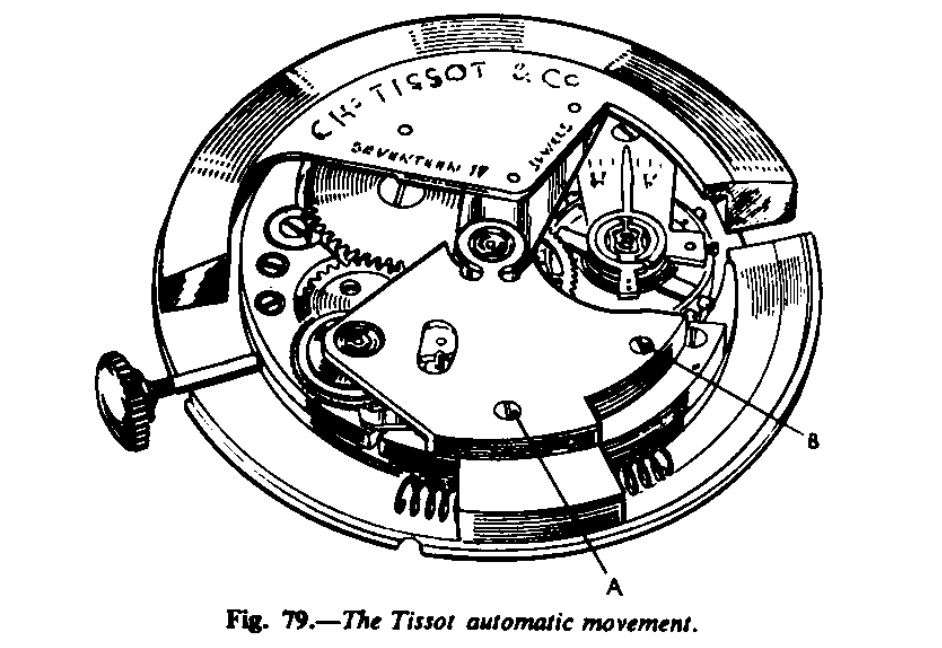
The rotor oscillates a segment of a circle and the movement is fitted with buffer springs. The rotor winds in one direction only. The action is as follows: Fixed to the rotor is a steel bar on the end of which are cut teeth A (Fig. 80), these teeth gearing into a rack cut on the end of a rocking bar B. Attached to this rocking bar is a ratchet wheel with pinion fixed to it. A click C engages in the ratchet wheel and the pinion gears into the transmission wheel. As the rotor moves to the left the rocking arm moves to the right and gathers up in a full movement three teeth of the ratchet, when the rotor returns to the right the ratchet wheel is moved forward to the right, and is held up in position by the click D, until eventually the click of the mainspring ratchet wheel takes over.
To dismantle, first release the click D (Fig. 80) so that the mainspring click holds the main ratchet wheel. Then remove the two screws A, B (Fig. 78). Lift the top plate of the automatic work off. The rotor can now be lifted free of the movement. Remove the rocking bar. To clean, remove the three screws holding the rocking bar ratchet; it is essential that the bearing of this wheel shall be perfectly clean and free.
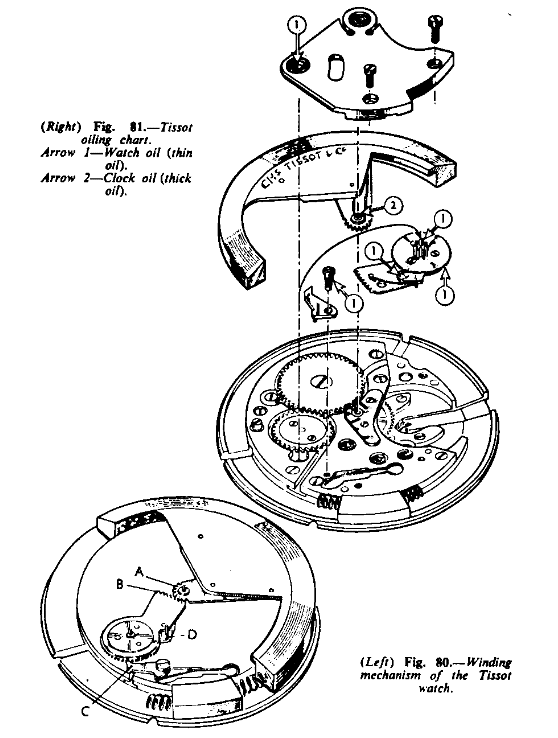
When reassembling the rocking bar, oil the bearing of the ratchet wheel with watch oil before screwing it into position. Place the rotor position and hold the rotor against the right-hand buffer spring; now place the rocking bar in position so that the last space of the rack teeth embraces the first tooth of the steel rack attached to the rotor. It is then certain that the rack of the rotor engages for the full segment of movement of the teeth of the rocking bar.
The rotor must not bank on the teeth of the rocking bar rack, but on the bumper springs. Fig. 80 shows the correct position. Place click D in position, Fig. 80, with its spring, and then the bridge.
Oil the pivots of the rotor with clock oil and the pivots of the rocking arm with watch oil. Apply a little watch oil to the teeth of the rocking arm ratchet wheel. Oil the shoulders of the two clicks controlling the rocking arm ratchet wheel with watch oil, sparingly. See Fig. 81, the oiling chart.
The instructions given by Messrs. Tissot when re-assembling are as follows: The automatic winding mechanism of a Tissot watch is remarkably simple yet in order to secure perfect running, its assembling requires the greatest accuracy. Therefore, we particularly insist on the importance of the following directions to ascertain that all parts are correctly located.
1. Move the rotor to and fro on the buffer springs, to make sure that the racks are properly meshed. The rotor should non stop before reaching either buffer spring. If it stops before the end of the swing, the respective position of the racks must be altered. They should gear as shown in Fig. 80.
2. Check the position of the rotor: it should touch neither plate nor case.
3. Control the end-shake of the rotor and of the small ratchet.
The end-shake should not exceed 2/100 of a millimetre.
4. Make sure that both racks are positioned on the same level.
5. Examine the retaining click work. The small ratchet is to move by three teeth forward at each useful oscillation of the rotor.
6. Check the end-shake of the retaining click.